PTC Heating Device

Pending Publication Date: 2021-09-02
EBERSPACHER CATEM HERMSDORF GMBH & CO KG
View PDF0 Cites 0 Cited by
  • Summary
  • Abstract
  • Description
  • Claims
  • Application Information

AI Technical Summary

Benefits of technology

[0007]The present invention is based on the problem of specifying a PTC heating device of the kind mentioned at the outse

Problems solved by technology

This is not always easy when the contact

Method used


Image

  • PTC Heating Device
  • PTC Heating Device

Examples


Example

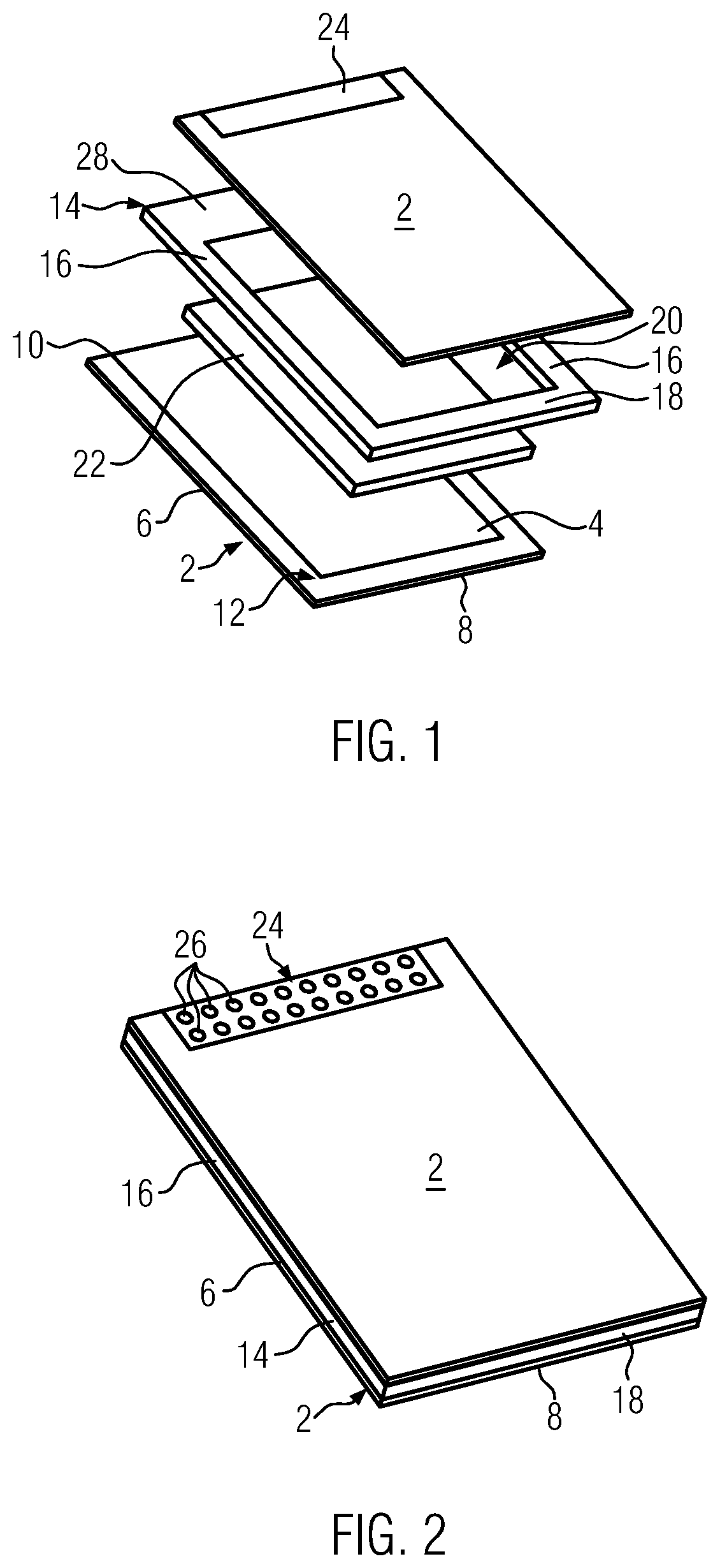
[0021]Provided with reference numeral 2 in FIG. 1 are two ceramic plates as examples of electrically insulating plates, which on oppositely disposed inner surfaces are provided with a metallization 4 that is spaced from the longitudinal edges, marked with reference numeral 6, of the ceramic plate 2 and a lower edge 8 and extends up to an upper edge 10. An electrically non-conductive U-shaped strip 12 is thereby provided on oppositely disposed inner surfaces of the respective ceramic plates 2. A frame element made of a ceramic material, denoted by reference numeral 14, has longitudinal tie members 16 and a lower transverse tie member 18, their width being matched to the width of the U-shaped strip 12. The frame element 14 is presently formed from aluminum oxide. The frame element 14 forms a recess 20 in which a PTC element 22 can be received with a small transverse spacing. In the exploded view according to FIG. 1, this PTC element 22 is still disposed below the frame element 14.

[002...


PUM


Abstract

A PTC heating device includes a PTC element and a frame element which forms a recess circumferentially surrounding the PTC element and being covered on both sides by electrically insulating plates that interact with the frame element for sealing the PTC element in the recess. In order to create a PTC heating device which allows for a reliable electrical connection of the PTC element to a power source while reliably sealing the PTC element in the recess, the insulating plates each be provided with a metallization that is connected, in an electrically conductively manner, to the PTC element. The metallization is connected in an electrically conductively manner, to an associated contact surface provided on the outer surface of the electrically insulating plate for the electrical connection of a power source to the PTC heating device.

Description

BACKGROUND OF THE INVENTION1. Field of the Invention[0001]The present invention relates to a PTC heating device with a PTC element and a frame element that forms a recess circumferentially surrounding the PTC element and being covered on both sides by electrically insulating plates that interact with the frame element for sealing the PTC element in the recess.2. Background of the Invention[0002]Such a PTC heating device is known from EP 1 921 896 A1.[0003]In the previously known PTC heating device as well as with the present invention, the frame element is typically formed from electrically insulating plastic material. The frame element is also referred to as a position frame. It fully surrounds the PTC element circumferentially. The PTC element is slightly thicker than the frame element so that the main side surfaces of the PTC element protrude beyond the frame element. The main side surfaces of the PTC element are those surfaces of the regularly cuboid-shaped PTC element via which...

Claims


Application Information

Patent Timeline
IPC IPC(8): H05B3/28H05B3/06
CPCH05B3/283H05B2203/02H05B3/06H05B3/02H05B3/04H05B3/20H05B3/50H05B2203/023B60H1/2215F24H9/1872
Inventor KÜMPEL, ANDREASKNÜPFER, YVES
Owner EBERSPACHER CATEM HERMSDORF GMBH & CO KG
Why Eureka
Try Eureka