LED lighting, connecting copper sheet and continuous connecting copper sheet

Inactive Publication Date: 2022-03-24
GUANG ZHOU TING SHEN ELECTRIC
View PDF0 Cites 0 Cited by
  • Summary
  • Abstract
  • Description
  • Claims
  • Application Information

AI Technical Summary

Benefits of technology

[0014]The advantageous effects of the present invention compared with the prior art are as follows: The first fixing sheet is formed into the C shape and the shape is similar to that of the pin, which facilitates the insertion and positioning of the pin, and realizes a reliable electrical connection with the LED lamp pin after riveting. The second fixing sheet is formed into the V shape and can clamp the wire core of the connecting wire after riveting to ensure the electrical connection between the connecting copper sheet and the connecting wire. The third fixing sheet is formed into the V shape and can clam

Problems solved by technology

The existing connection methods have the following defects: (1) The connection between the LED lamp and the wire requires assembly through a dedicated connector, which leads to a cumbersome manufacturing process, so the LED assembly consumes a lot of manpower and man-hours.
(2) The copper terminal that connects with the connecting wire by pressure riveting consumes

Method used


Image

  • LED lighting, connecting copper sheet and continuous connecting copper sheet
  • LED lighting, connecting copper sheet and continuous connecting copper sheet
  • LED lighting, connecting copper sheet and continuous connecting copper sheet

Examples


Example

Embodiment 1

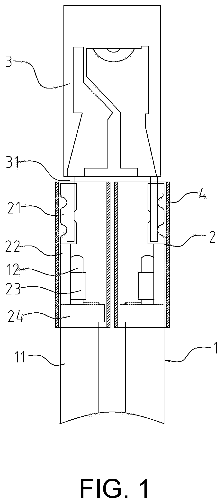
[0023]As shown in FIG. 1, an LED lighting includes an LED lamp 3, a connecting wire 1, and a connecting copper sheet 2 used to connect the LED lamp 3 and the connecting wire 1.

[0024]As shown in FIG. 1, the LED lamp 3 can be an LED light bar, an LED bulb or a simple light-emitting diode. The LED lamp 3 has two leading-out pins: positive and negative. The pins are electrically connected through the connecting wire 1 and the external power supply charges LED lamp 3 through the connecting wire 1.

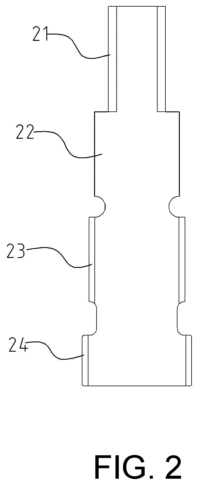
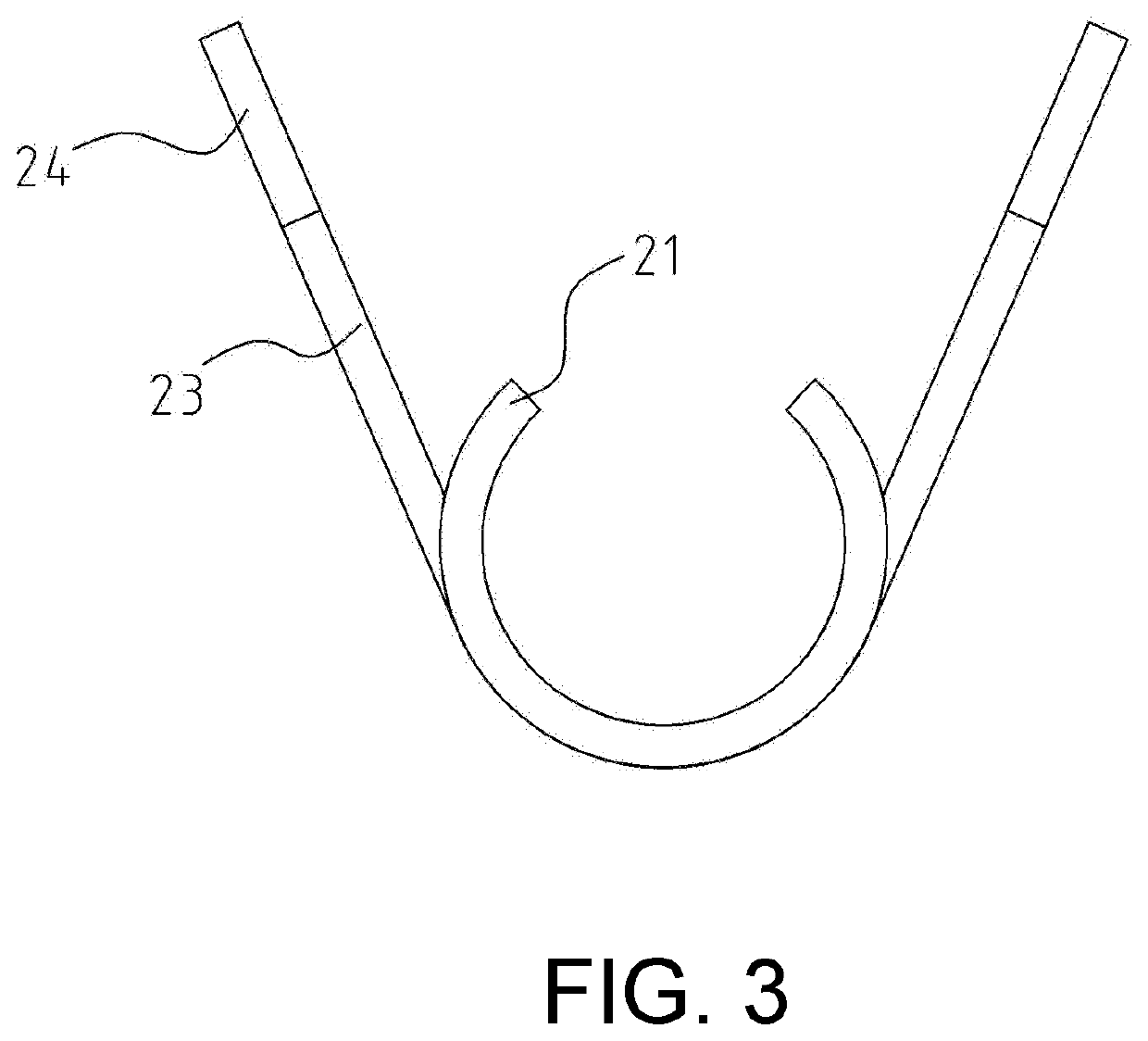
[0025]As shown in FIGS. 2 to 4, the connecting copper sheet 2 includes a first fixing sheet 21 used to connect with the pin 31 of the LED lamp, the second fixing sheet 23 used to connect with the wire core 12 of the connecting wire 1, the third fixing sheet 24 used to connect with the sheath 11 of the connecting wire 1 and the copper strip 22 for connecting the first fixing sheet 21 and the second fixing sheet 23. The connecting copper sheet 2 is formed by integrated stamping and ben...

Example

Embodiment 2

[0028]As shown in FIGS. 6 and 7, what is different from Embodiment 1 is that the connecting copper sheet includes the first fixing sheet 21, the second fixing sheet 23 and the third fixing sheet 24. The first fixing sheet 21, the second fixing sheet 23 and the third fixing sheet 24 are concatenated in series. The length of the third fixing sheet 24 is longer than that of the second fixing sheet 23. The length of the second fixing sheet 23 is longer than that of the first fixing sheet 21. The width of the third fixing sheet 24 is shorter than that of the second fixing sheet 23. The width of the second fixing sheet 23 is shorter than that of the first fixing sheet 21. The first fixing sheet 21, the second fixing sheet 23 and the third fixing sheet 24 are all V-shaped or U-shaped. In order to realize large-scale automated production, the connecting copper sheet 2 is continuously produced by a long copper strip to form a continuous connecting copper sheet, that is, the adjac...


PUM

PropertyMeasurementUnit
Lengthaaaaaaaaaa
Widthaaaaaaaaaa
Heataaaaaaaaaa

Abstract

An LED lighting includes an LED lamp, a connecting wire, and a connecting copper sheet used to connect the LED lamp and the connecting wire. The connecting copper sheet includes a first fixing sheet used to connect with the pin of the LED lamp, a second fixing sheet used to connect with the core wire of the connecting wire, a third fixing sheet used to connect with the sheath of the connecting wire, and a copper strip for connecting the first fixing sheet and the second fixing sheet. The length of the third fixing sheet is longer than that of the second fixing sheet. The width of the third fixing sheet is shorter than that of the second fixing sheet. The third fixing sheet is concatenated with the second fixing sheet, and the connecting copper sheet is sheathed with an insulating sleeve.

Description

CROSS-REFERENCE TO RELATED APPLICATION[0001]This application claims the priority benefit of China application serial no. 202022124599.3, filed on Sep. 24, 2020. The entirety of the above-mentioned patent application is hereby incorporated by reference herein and made a part of this specification.BACKGROUNDTechnical Field[0002]This application relates to the field of LED, particularly to an LED lighting and a connecting copper sheet.Description of Related Art[0003]At present, there are two connection methods in the LED production industry: 1. The pins of an LED lamp are plugged into a soft core shell; a copper terminal connects with a connecting wire by pressure riveting, and then a soft head shell is assembled; finally, the soft core shell is plugged into the soft head shell to assemble. 2. An LED lamp and wire are welded, and the welded part is sheathed with a shrink film. The existing connection methods have the following defects: (1) The connection between the LED lamp and the wi...

Claims


Application Information

Patent Timeline
IPC IPC(8): F21V23/00H01L33/62
CPCF21V23/001F21Y2115/10H01L33/62B32B15/01H01B1/026F21V19/0025H01R4/185H01R33/06F21V19/0005
Inventor WANG, CHIA-CHUN
Owner GUANG ZHOU TING SHEN ELECTRIC
Why Eureka
Try Eureka