[0019]The present invention has been made to overcome such a drawback and, it is an object of the present invention to provide an image display device which can obtain high brightness, high reliability and a prolonged lifetime by suppressing the breakage and the deformation of spacers which hold a hermetically sealed space surrounded by a face substrate, a back substrate and a frame body.
[0022]Further, another image display device according to the present invention includes a face substrate which forms a
black matrix film in which a plurality of opening portions is formed,
phosphor layers having a plurality of colors which are arranged in a state that the
phosphor layers close the opening portions and extend over the
black matrix film, and an
anode electrode which is made of a
metal thin film and covers the
phosphor layers and the
black matrix film on an inner surface thereof, a back substrate which forms a plurality of scanning
signal lines which extend in one direction, are arranged in parallel in another direction which intersects one direction, and to which scanning signals are sequentially applied in another direction, a plurality of
image signal lines which extend in another direction and are arranged in parallel in one direction so as to intersect the scanning
signal lines, and
electron sources which are provided in the vicinities of respective intersecting portions of the scanning
signal lines and the
image signal lines on an inner surface thereof, and faces the face substrate in an opposed manner with a predetermined distance therebetween, a frame body which is interposed between the face substrate and the back substrate in a state that the frame body surrounds a display region and holds the predetermined distance, a plurality of distance holding members which are arranged to be overlapped to the scanning
signal lines and extend in the same direction with the scanning
signal lines between the face substrate and the back substrate and within the display region, and a conductive
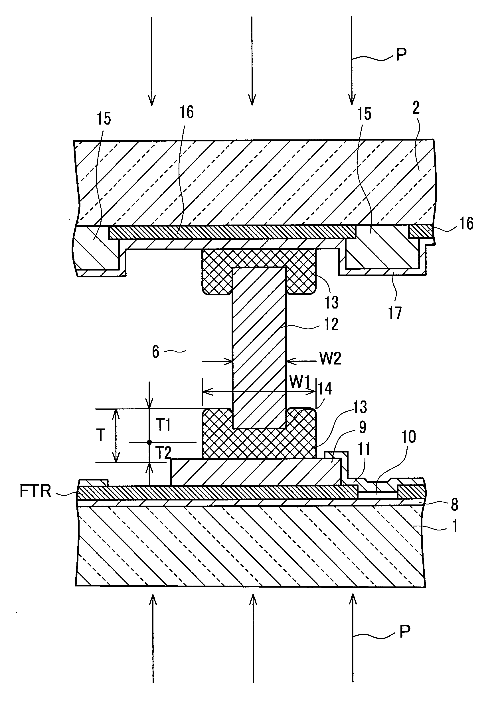
adhesive material which joins by adhesion end surfaces of the distance holding members to the face substrate and the back substrate respectively. The end surfaces of the frame body and the face substrate and the back substrate are hermetically sealed to each other by way of a sealing material. The distance holding members are jointed to both substrates in a state that the distance holding members bite into the conductive adhesive material in the
depth direction of a
coating thickness of the conductive adhesive material and hence, at adhesion surfaces of the distance holding members with the face substrate and the back substrate, the distance holding members are electrically and mechanically firmly joined to the substrates. Due to such a constitution, the present invention can overcome the drawbacks of the related art.
[0024]According to the image display device of the present invention, the distance holding members are jointed to both substrates in a state that the end surfaces of the distance holding members bite into the conductive adhesive material in the
depth direction of a
coating thickness of the conductive adhesive material and hence, it is possible to firmly ensure the more reliable electric connection and mechanical fixing between the distance holding members and the back substrate as well as between the distance holding members and the face substrate using the distance holding members. Accordingly, it is possible to surely prevent the breakage and the deformation of the distance holding members or the deformation of the substrates or the like attributed to an
atmospheric pressure and hence, a high vacuum can be ensured by increasing the evacuation efficiency whereby it is possible to acquire an extremely excellent advantageous effect that an image display device which exhibits a prolonged lifetime, high brightness and high reliability can be obtained.

