

Fuel injection control device for internal combustion engine
- Summary
- Abstract
- Description
- Claims
- Application Information
AI Technical Summary
Benefits of technology
Problems solved by technology
Method used
Image

Examples
Embodiment Construction
[0014]An embodiment of the present invention will be described with reference to the drawings.
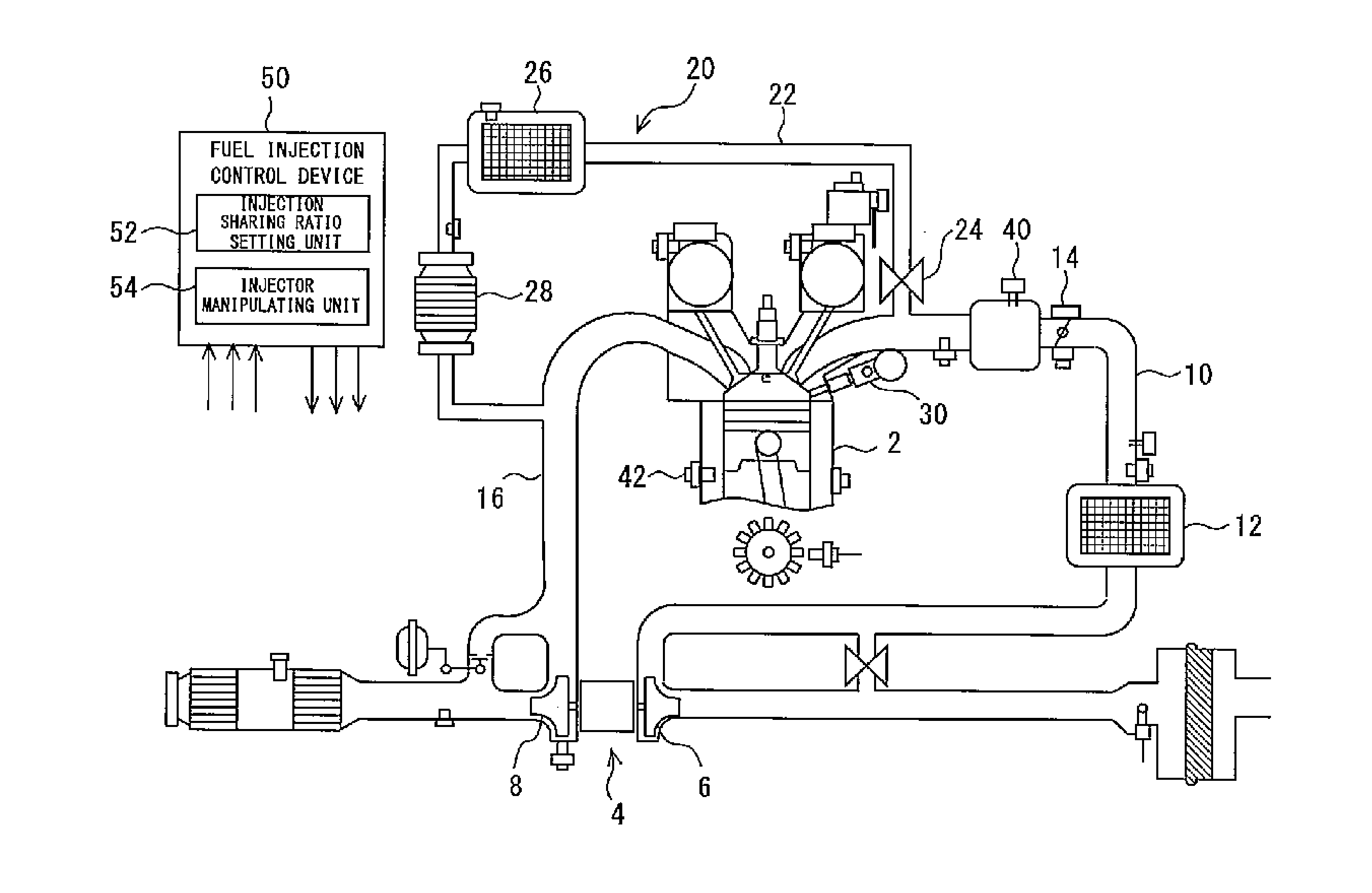
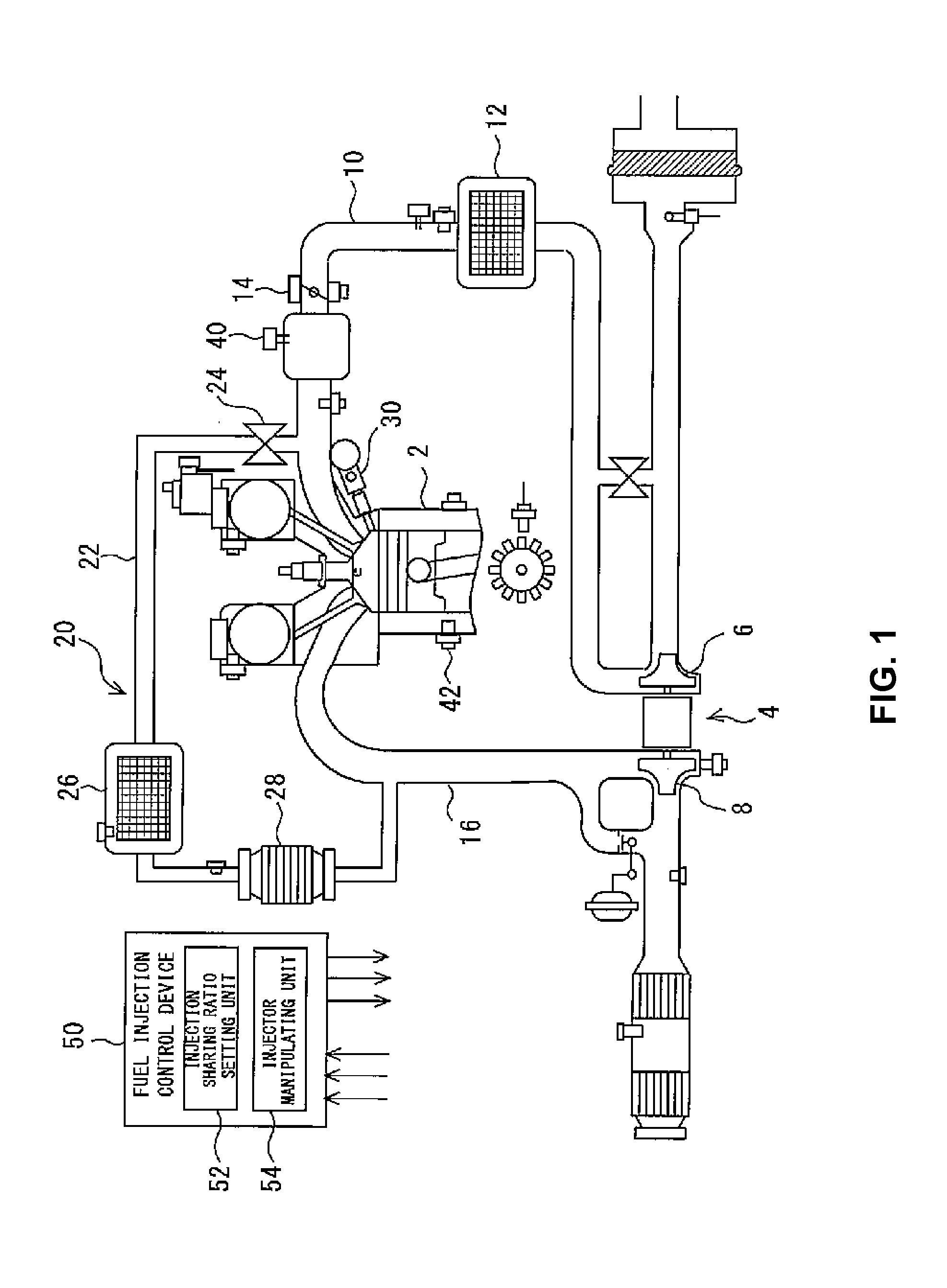
[0015]FIG. 1 is a diagram showing a system configuration of an internal combustion engine to which a fuel injection control device of the embodiment of the present invention is applied. The internal combustion engine according to the present embodiment is a spark ignition type four stroke reciprocal engine (hereinafter, simply called an engine) which uses gasoline as a fuel. The engine according to the present embodiment includes a turbo supercharger 4 which compresses air (fresh air) by using energy of exhaust gas. A compressor 6 of the turbo supercharger 4 is disposed in an intake passage 10, and a turbine 8 is disposed in an exhaust passage 16. An inter cooler 12 is attached downstream of the compressor 6 in the intake passage 10, and a throttle 14 is disposed further downstream thereof. Further, the supercharged engine according to the present embodiment is loaded with an EGR device 20 ...
PUM
 Abstract
Description
Claims
Application Information