Elevator rope sway detection device
a detection device and elevator rope technology, applied in the direction of elevators, instruments, computer control, etc., can solve the problems of passengers being entrapped, damaged, or caught by the rope contact hoistway device, and achieving the effect of preventing incorrect accurate detection of elevator rope sways
- Summary
- Abstract
- Description
- Claims
- Application Information
AI Technical Summary
Benefits of technology
Problems solved by technology
Method used
Image
Examples
embodiment 1
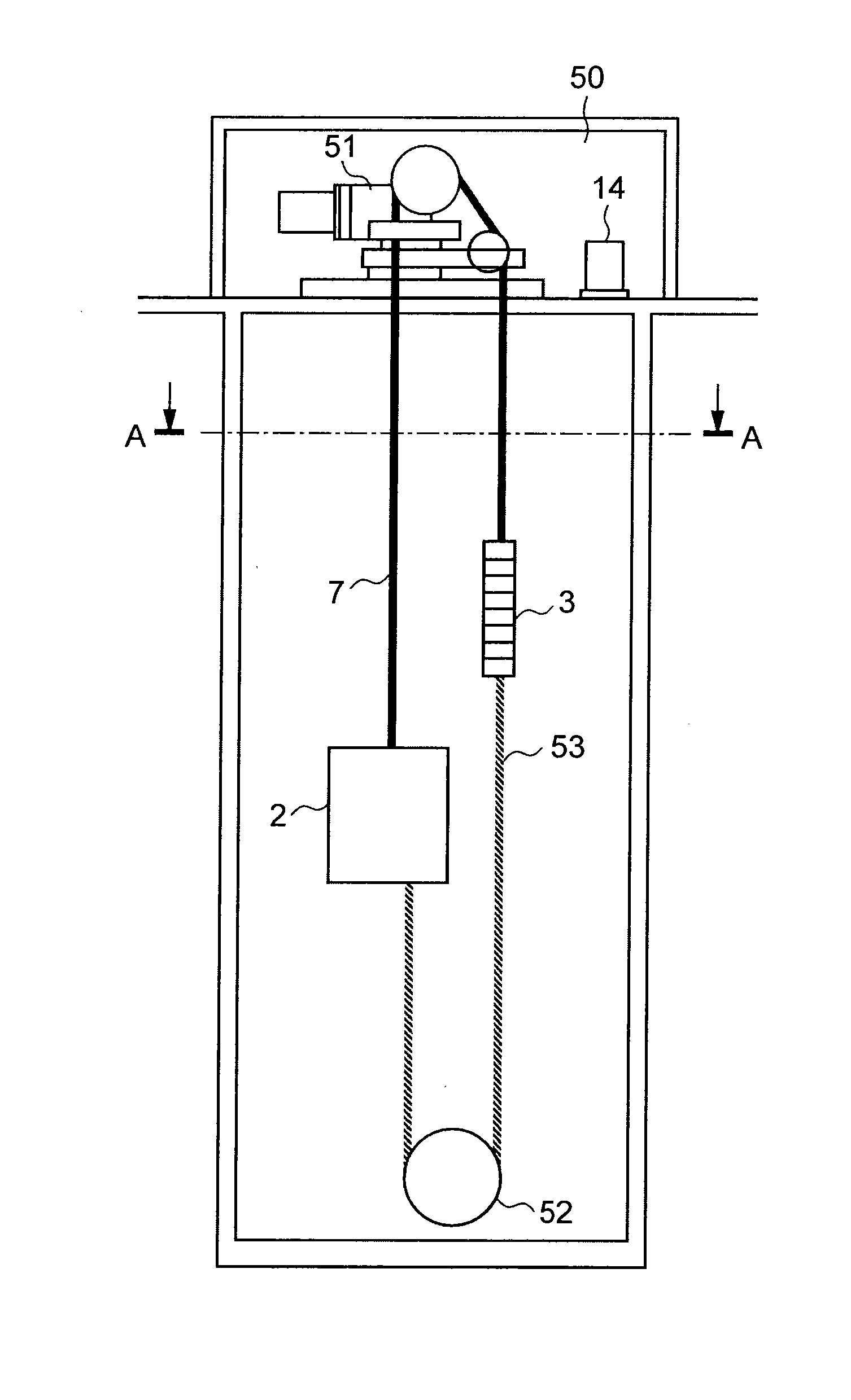
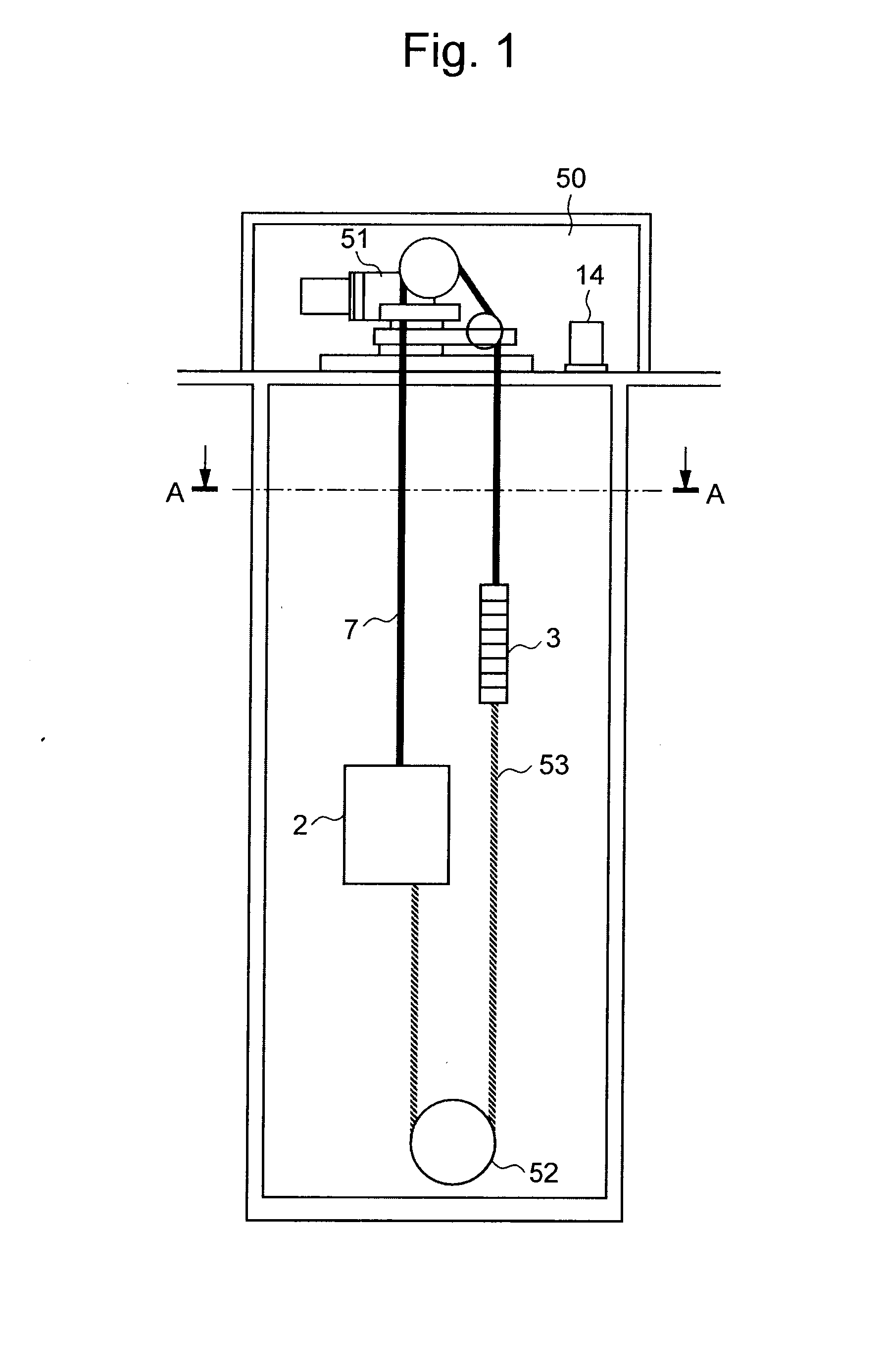
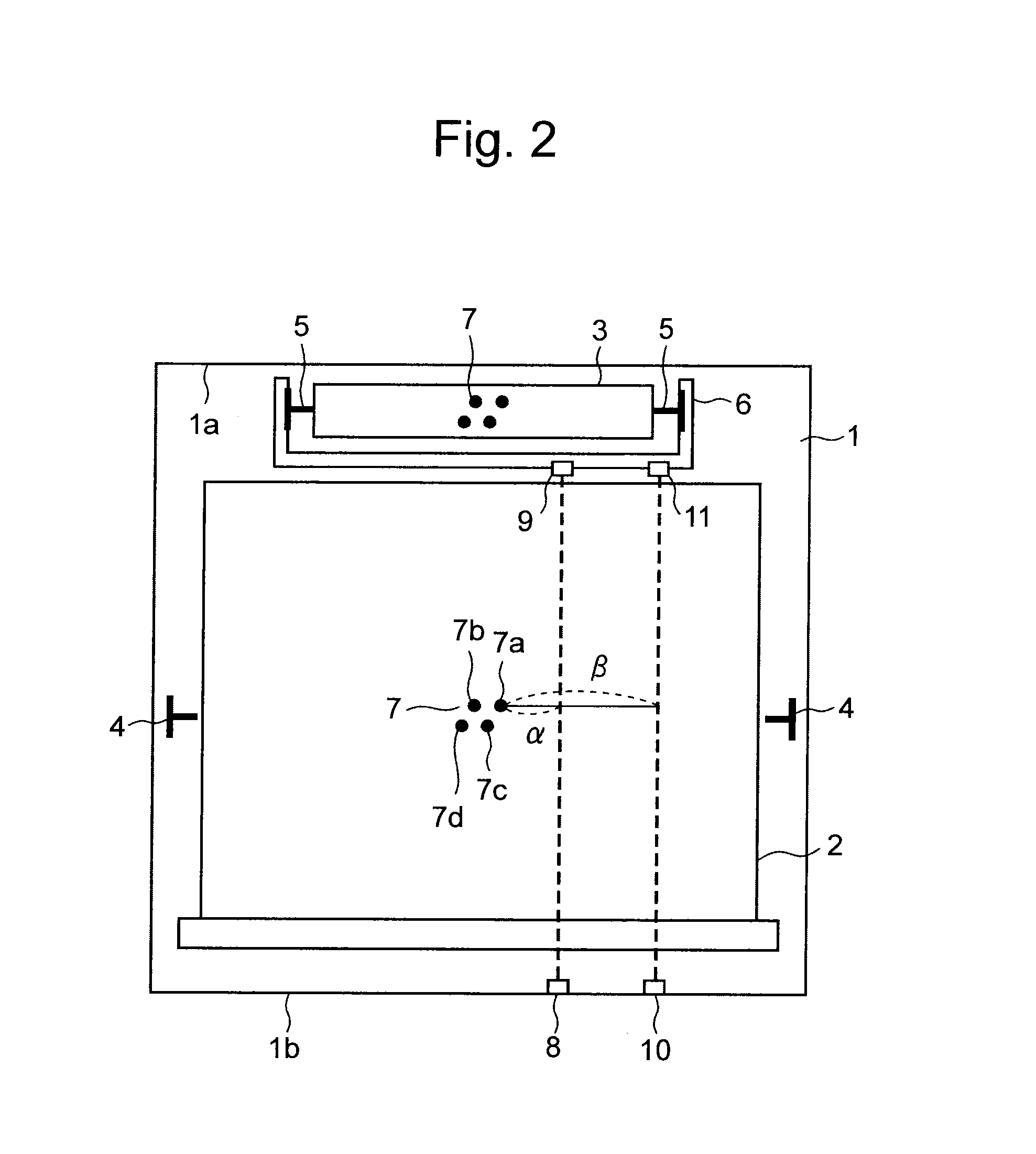
[0032]FIG. 1 is a structural view of an elevator of Embodiment 1 according to the present invention; FIG. 2 is a plan view showing the inside of a hoistway in the elevator of Embodiment 1 according to the present invention; FIG. 3 is a block diagram illustrating a configuration of an elevator rope sway detection device of Embodiment 1 according to the present invention. In FIGS. 1 to 3, illustrated are the hoistway 1 of the elevator, a car 2 travelling upward and downward in the hoistway 1, a counter weight 3 travelling upward and downward in the hoistway 1 in reverse directions of the car 2, a pair of car guide rails 4 placed in the hoistway 1 for guiding the car 2 to travel upward and downward, a pair of counter weight guide rails 5 placed in the hoistway 1 for guiding the counter weight to travel upward and downward, a support bracket 6 for supporting the counter weight guide rails 5, placed on, for example, a hoistway wall 1a, i.e. a back side wall adjacent to the counter weight...
embodiment 2
[0057]FIG. 10 shows an example of an elevator rope sway detector of Embodiment 2 according to the present invention. The rope sway detector shown in FIG. 10 includes sway detection means, i.e. beam emitting components 8 and 10 and beam receiving components 9 and 11. The beam emitting component 8 and the beam receiving component 9 configure a detection line that is positioned the predetermined distance α apart from the normal suspension position of the above-car suspender part 7a, to detect a sway of a first level; the beam emitting component 10 and the beam receiving component 11 configure another detection line that is positioned the predetermined distance β apart from the normal suspension position of the above-car suspender part 7a, at a height shifted in a height direction by a predetermined distance H from the first sway detection line, to detect a sway of a second level. FIG. 10 shows only the above-car suspender part 7a, for simplification.
[0058]More specifically, when the ab...
embodiment 3
[0074]FIG. 19 illustrate examples that indicate where to install, in a hoistway, an elevator rope sway detection device of Embodiment 3 according to the present invention. FIG. 19 (a) indicates a position 60 provided for installing a main rope sway detector, and FIG. 19 (b) indicates a position 61 provided for installing a compensation rope sway detector. An example is shown in which the main rope sway detector position 60 is located at the maximum amplitude position of the main rope, when the car is located at a position where the building shake period becomes identical to the first order vibration mode period of the main rope determined by the main rope length, the main rope tension, and the main rope linear density. An example is shown in which the compensation rope sway detector position 61 is located at the maximum amplitude position of the compensation rope, when the car is located at a position where the building shake period becomes identical to the second order vibration mo...
PUM
 Abstract
Description
Claims
Application Information
 - R&D
- Intellectual Property
- Life Sciences
- Materials
- Tech Scout
- Unparalleled Data Quality
- Higher Quality Content
- 60% Fewer Hallucinations
Browse by: Latest US Patents, China's latest patents, Technical Efficacy Thesaurus, Application Domain, Technology Topic, Popular Technical Reports.
© 2025 PatSnap. All rights reserved.Legal|Privacy policy|Modern Slavery Act Transparency Statement|Sitemap|About US| Contact US: help@patsnap.com


