Tire shape testing device and tire shape testing method
a tire shape and testing device technology, applied in vehicle tyre testing, television systems, instruments, etc., can solve problems such as difficulty in accurately forming tires, and achieve the effect of easy testing
- Summary
- Abstract
- Description
- Claims
- Application Information
AI Technical Summary
Benefits of technology
Problems solved by technology
Method used
Image
Examples
first embodiment
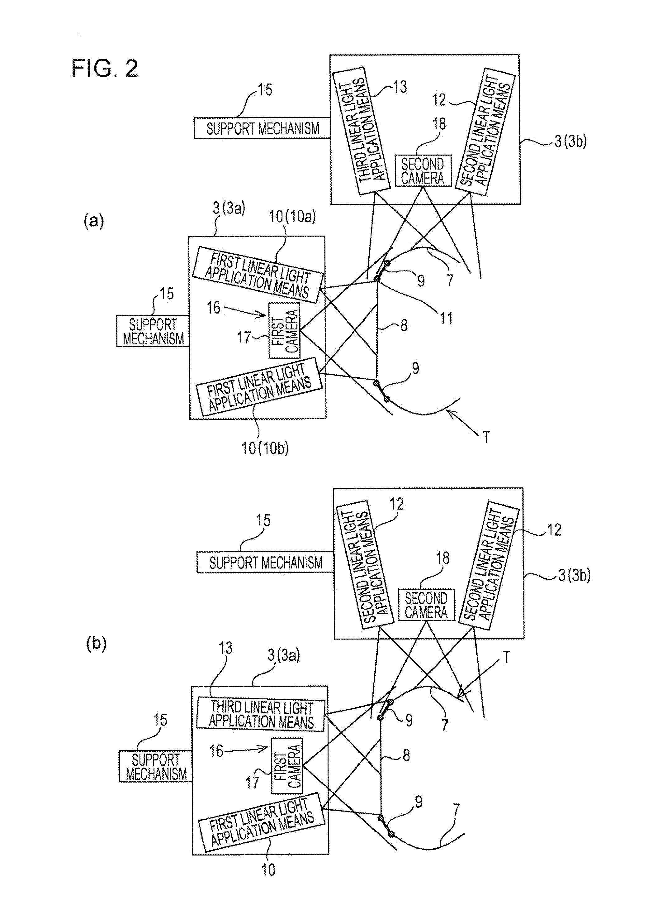
[0035]In recent years, there has been a demand for a shape test for testing not only sidewall sections and a tread section but also shoulder sections of a tire, in other words, for testing the entire surface of a wide tire. To comply with such a demand, a tire shape testing device of the present invention is capable of detecting the surface shapes of sidewall sections, a tread section, and shoulder sections of a tire.
[0036]A tire shape testing device according to the present embodiment will now be described in detail.
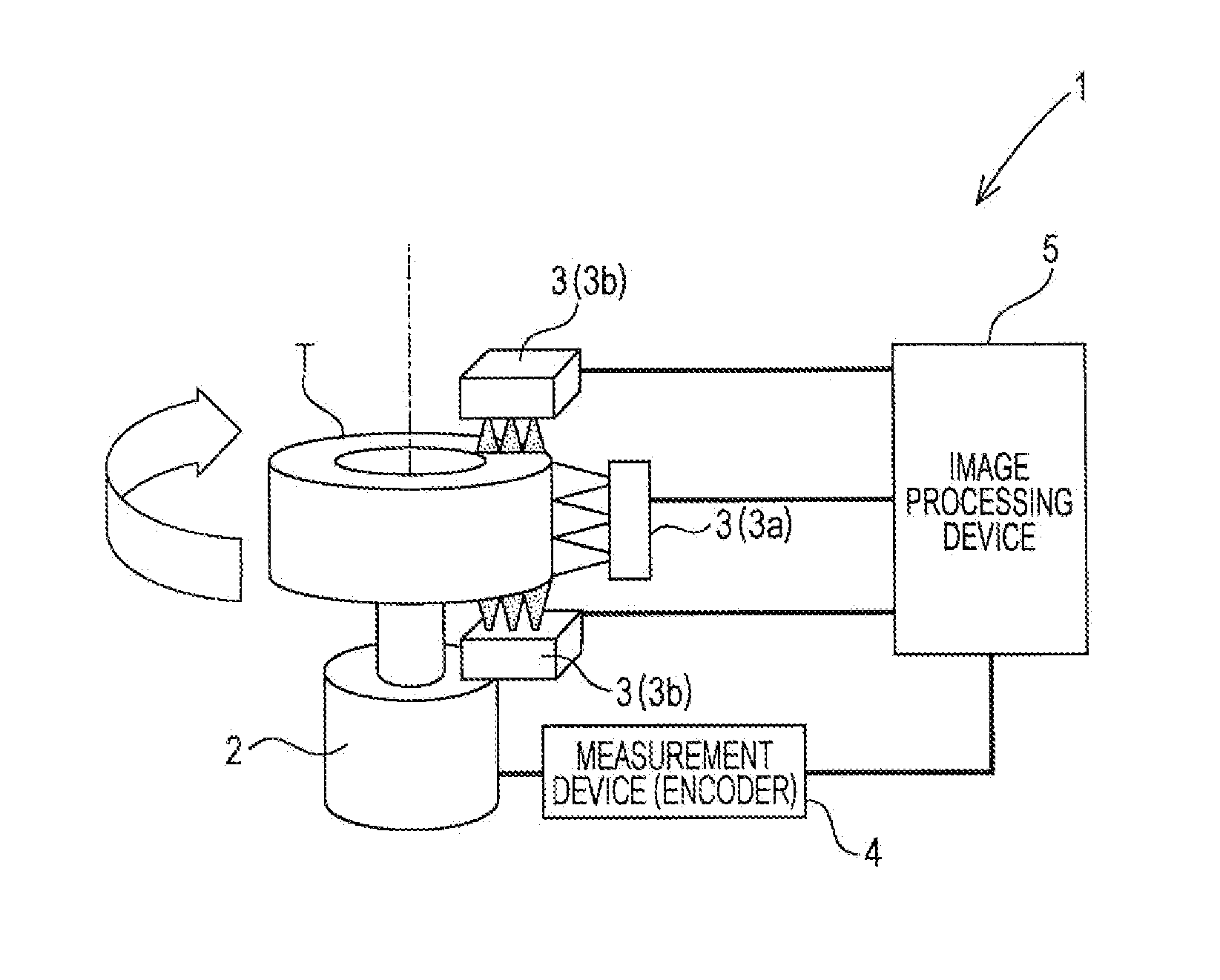
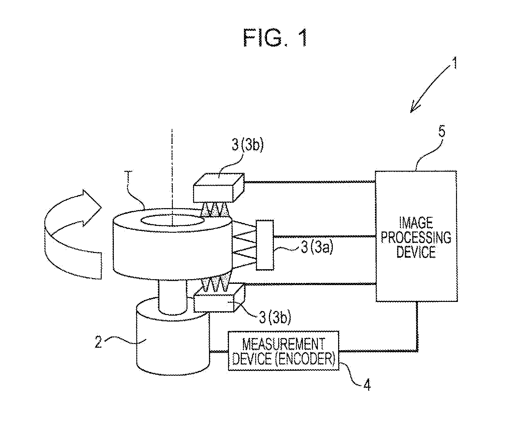
[0037]As illustrated in FIG. 1, a tire shape testing device 1 includes a tire rotator 2, sensor units 3, a measuring device 4, and an image processing device 5.
[0038]The tire rotator 2 is a rotating device including a motor or the like that rotates a tire T, which is a subject of the shape test, around a rotation axis of the tire T. The tire rotator 2 rotates the tire T at a rotational speed of, for example, 60 rpm. Images of the surface shape of the tire T are captured...
second embodiment
[0073]In the above-described first embodiment, the third linear light application means 13 is included in one of the sensor units 3 (in the first sensor unit 3a or the second sensor unit 3b). In the second embodiment, the third linear light application means 13 is disposed outside the sensor units 3a and 3b.
[0074]As illustrated in FIG. 3, the third linear light application means 13 is disposed between the first sensor unit 3a and the second sensor unit 3b, and an optical center of the third linear light application means 13 is directed toward the shoulder section 9.
[0075]Specifically, the third application means irradiates, with a linear light beam, a region from the tread section 8 to beyond the boundary section between the tread section 8 and the shoulder section 9 and a region from the shoulder section 9 to beyond the boundary section between the shoulder section 9 and the sidewall section 7. In other words, the third linear light application means 13 irradiates the entire regio...
third embodiment
[0083]In the above-described first and second embodiments, the image capturing means 16 (the first camera 17 and the second camera 18) may include an ordinary CCD camera, and the structure thereof is not particularly limited.
[0084]However, image capturing means 16 according to a third embodiment has a specific structure including a plurality of fixed focal length lenses. For convenience of explanation, linear light beams reflected by the tire surface are referred to as reflected light beams.
[0085]As illustrated in FIG. 4, a first camera 17 includes a detector 20 including CCD elements that detect (capture images of) linear light beams, a plurality of (for example, three) lenses 21 that focus the images of the linear light beams on the detector 20, and region setting mirrors 22 that set image capturing regions to be captured through the lenses 21.
[0086]Each lens 21 is a fixed focal length lens 21, and the lenses 21 are arranged in a direction along the detector 20 with predetermined ...
PUM
 Abstract
Description
Claims
Application Information
 - R&D
- Intellectual Property
- Life Sciences
- Materials
- Tech Scout
- Unparalleled Data Quality
- Higher Quality Content
- 60% Fewer Hallucinations
Browse by: Latest US Patents, China's latest patents, Technical Efficacy Thesaurus, Application Domain, Technology Topic, Popular Technical Reports.
© 2025 PatSnap. All rights reserved.Legal|Privacy policy|Modern Slavery Act Transparency Statement|Sitemap|About US| Contact US: help@patsnap.com


