Method for Mapping Packets to Network Virtualization Instances

a virtualization instance and packet technology, applied in the field of communication networks, can solve the problems of increasing the delay in implementing a forwarding decision, increasing the latency associated with packet forwarding, and expensive design of network elements to keep the state of this natur

Active Publication Date: 2014-01-02
EXTREME NETWORKS INC
View PDF15 Cites 123 Cited by
  • Summary
  • Abstract
  • Description
  • Claims
  • Application Information

AI Technical Summary

Benefits of technology

[0011]An operating system adds an application signature as a tag in a packet header. In one embodiment the tag is inserted as a Q-tag in an Ethernet header. When a network element receives the tagged packet, it uses the tag alone or in combination with one or more additional header fields to map the packet to a network virtualization identifier segregating the application traffic on the network. Services are applied to packets according to network virtualization identifier to enable distributed application of services without requiring network elements to maintain state associated with packet flows.

Problems solved by technology

Unfortunately, traffic from a given application may include multiple TCP / UDP sessions where Layers 3 and 4 of the seven layer networking stack are being used for transport control, or multiple HTTP sessions where layer 7 (application layer) is being used to implement transport control.
Designing the network elements to keep state of this nature is expensive from a network element design standpoint.
Likewise, requiring the network elements to associate packets with flows in connection with providing services can also increase latency associated with packet forwarding, as the increased processing associated with performing this correlation translates to increased delay in implementing a forwarding decision.
Further when the data itself is encrypted, it may not be possible to determine which packet is associated with a particular application, so even if it were possible to maintain state it may not be possible to implement per packet services on the network.

Method used


Image

  • Method for Mapping Packets to Network Virtualization Instances
  • Method for Mapping Packets to Network Virtualization Instances
  • Method for Mapping Packets to Network Virtualization Instances

Examples


Embodiment Construction

[0018]The following detailed description sets forth numerous specific details to provide a thorough understanding of the invention. However, those skilled in the art will appreciate that the invention may be practiced without these specific details. In other instances, well-known methods, procedures, components, protocols, algorithms, and circuits have not been described in detail so as not to obscure the invention.

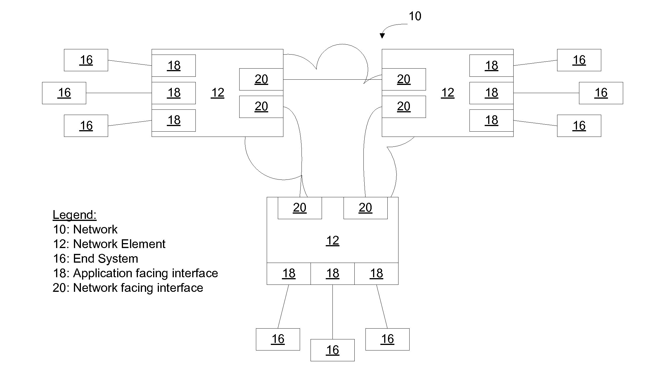
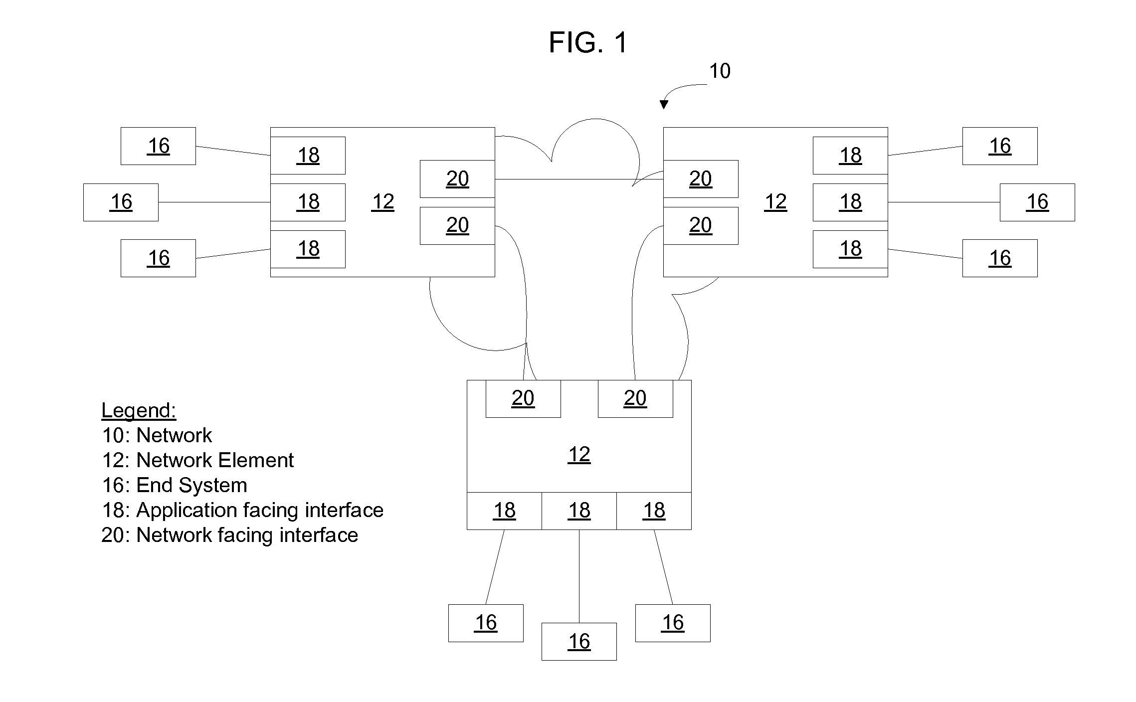
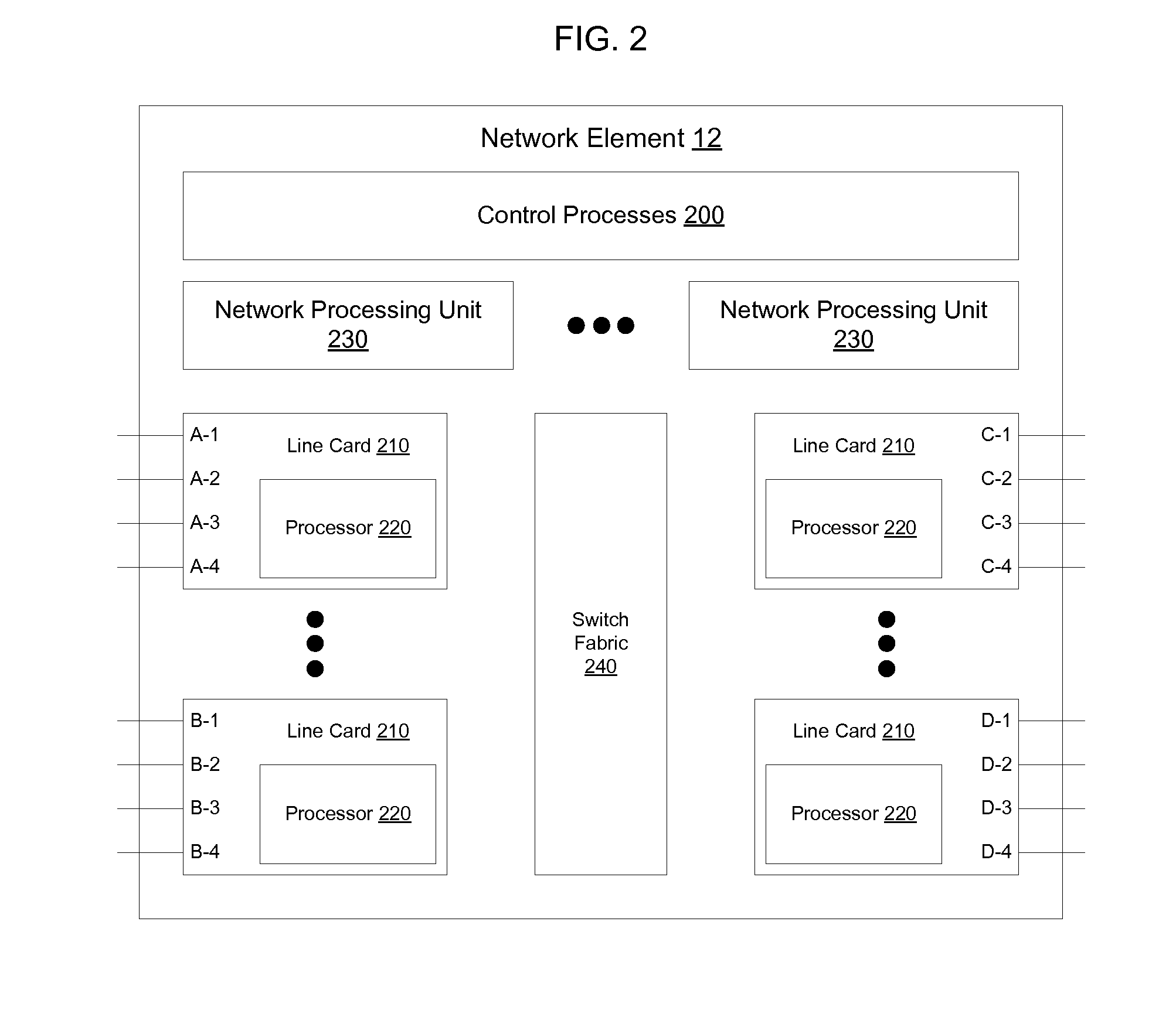
[0019]FIG. 1 illustrates an example of a network 10 in which a plurality of network elements 12 such as switches and routers are interconnected to transmit packets of data. Network elements 12 receive packets from end systems 16, process the packets, and forward packets of data toward their destination on the network. End systems 16 include computers (FIG. 3), servers (FIG. 4), or other packet sources. An example network element 12 is discussed in greater detail below in connection with FIG. 2.

[0020]Network elements 12, in one embodiment, are access devices configured to ...


PUM


Abstract

An operating system adds an application signature as a tag in a packet header. In one embodiment the tag is inserted as a Q-tag in an Ethernet header. When a network element receives the tagged packet, it uses the tag alone or in combination with one or more additional header fields to map the packet to a network virtualization identifier segregating the application traffic on the network. Services are applied to packets according to network virtualization identifier to enable distributed application of services without requiring network elements to maintain state associated with packet flows.

Description

CROSS-REFERENCE TO RELATED APPLICATIONS[0001]None.BACKGROUND[0002]1. Field[0003]This application relates to communication networks and, more particularly, to a method for packet marking[0004]2. Description of the Related Art[0005]Data communication networks may include various switches, nodes, routers, and other devices coupled to and configured to pass data to one another. These devices will be referred to herein as “network elements”. Data is communicated through the data communication network by passing protocol data units, such as frames, packets, cells, or segments, between the network elements by utilizing one or more communication links. A particular protocol data unit may be handled by multiple network elements and cross multiple communication links as it travels between its source and its destination over the network.[0006]Applications, such as email applications, instant messaging applications, web browsers, and other applications running on end user devices transmit packe...

Claims


Application Information

Patent Timeline
Patent Type & Authority Applications(United States)
IPC IPC(8): H04L12/56
CPCH04L69/22H04L43/026H04L69/321H04L69/324
Inventor ASSARPOUR, HAMIDTERPSTRA, MARTEN
Owner EXTREME NETWORKS INC
Why Eureka
Try Eureka