
Labyrinth seal of a radial rolling contact bearing having a radial flange

a technology of radial rolling contact bearing and radial flange, which is applied in the direction of bearings, mechanical equipment, transportation and packaging, etc., can solve the problems of component integration in order to reduce the great variety of components of radial bearings, the sealing rings cannot be pressed together, and the cost is further increased. , to achieve the effect of good sealing effect, low friction coefficient and simple assembly

Inactive Publication Date: 2014-01-02
SCHAEFFLER TECH AG & CO KG
View PDF2 Cites 18 Cited by
  • Summary
  • Abstract
  • Description
  • Claims
  • Application Information

AI Technical Summary

Benefits of technology

The invention is a sealing arrangement that has a simple design and can achieve effective sealing with low friction. It includes a catch groove and a sealing ring with a retention element and a resilient member that has a sealing lip. The sealing gap extends from the catch groove to the hub flange and tapers outward in a radial direction. The narrow construction of the sealing gap prevents water from entering the sealing space and allows water to drain away via the axial opening. The sealing lip has high friction to provide effective sealing even with high levels of contamination. Overall, the invention provides a reliable and efficient sealing arrangement.

Problems solved by technology

It is problematic that both sealing rings cannot be pressed together in a simple manner in the rolling contact bearing space and therefore require two separate assembly steps.
It is further costly, owing to the complex shapings, to produce such sealing rings from rolling contact bearing steel or to integrate the sealing rings in the rolling contact bearing rings.
Therefore, component integration in order to reduce the great variety of components in radial bearings is not possible.

Method used


Image

  • Labyrinth seal of a radial rolling contact bearing having a radial flange
  • Labyrinth seal of a radial rolling contact bearing having a radial flange

Examples


Embodiment Construction

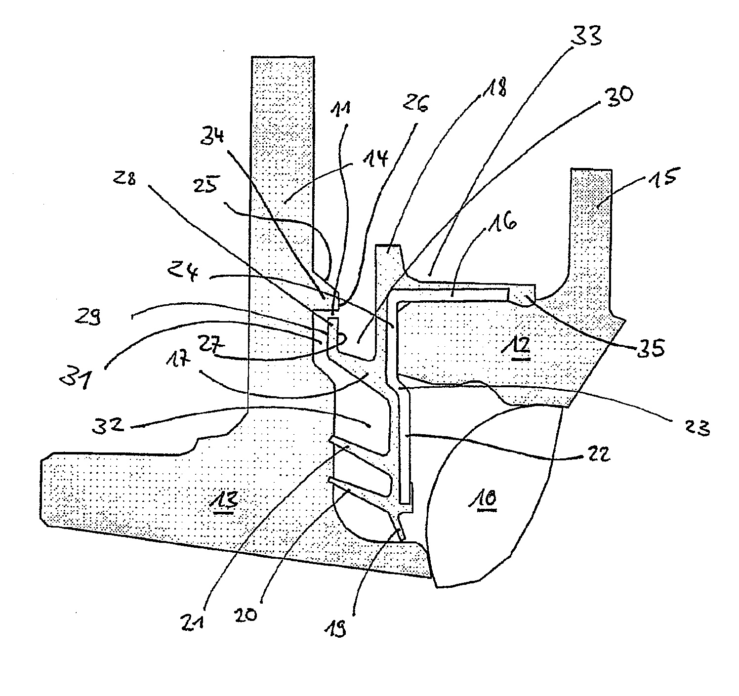
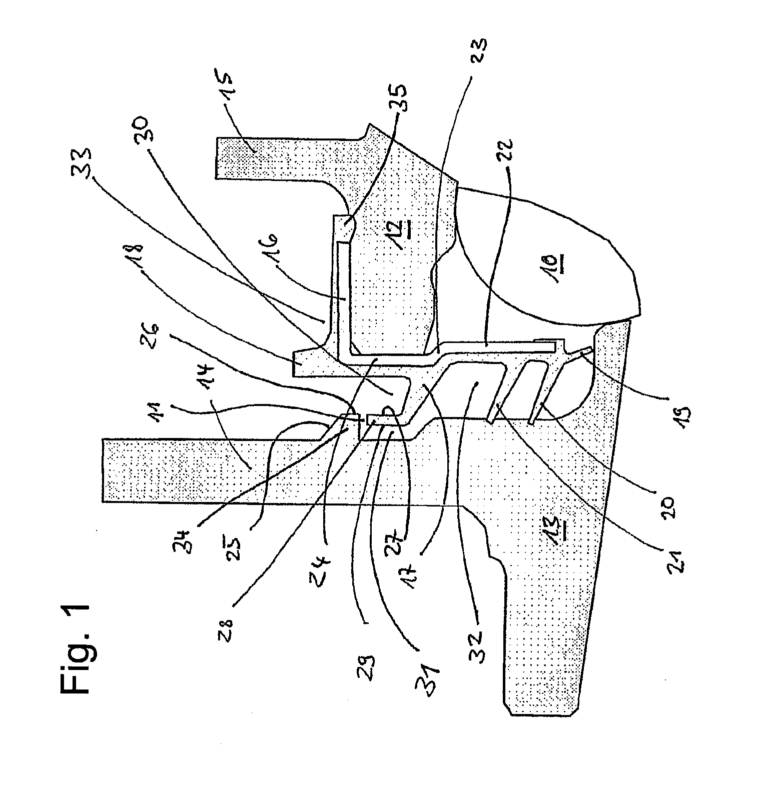
[0023]FIG. 1 shows a wheel-flange-side sealing arrangement for sealing a wheel bearing, whose wheel hub 13, outer ring 15 and roller member 10 are only partially illustrated. It is, for example, a wheel bearing unit, which can be secured to a wheel carrier with the flange 15 and which has a wheel flange 14 for securing a wheel rim.

[0024]The first sealing ring 24 is secured to an outer ring by means of a cylindrical securing element 16. The second sealing ring known from the prior art is not present as a separate component. Instead, the wheel flange 14 of the wheel hub 13 has taken over the functions thereof.

[0025]The radial continuation 18 of the resilient member 17 forms, together with the securing flange 15 of the wheel bearing, a radially outwardly positioned third catch groove 33. The first catch groove 30 is completely formed by the resilient member 17, in this embodiment an elastomer, and the second catch groove 32 adjoins the sealing gap 31 radially at the inner side between ...


PUM


Abstract

A seal assembly for sealing a radial rolling contact bearing, having a first sealing ring and a second sealing ring, wherein the two sealing rings can be rotated relative to each other about a common axis of rotation and together form a labyrinth seal, wherein a sealing gap of the labyrinth seal that extends substantially radially with respect to the axis of rotation is covered radially by an axial projection of the second sealing ring, and the sealing gap at the axial projection opens axially into a first catch channel of the first sealing ring. A hub of the radial rolling contact bearing forms the second sealing ring. Therefore, the second sealing ring is integrated into the hub flange, which means that the hub flange performs the function of the second sealing ring and to some extent helps to form the labyrinth seal.

Description

[0001]The invention relates to a first sealing ring and a second sealing ring, both sealing rings being able to be rotated relative to each other about a common rotation axis and together forming a labyrinth seal, a labyrinth seal sealing gap which extends substantially radially relative to the rotation axis being radially covered by an axial projection of the second sealing ring and the sealing gap at the axial projection opening axially in a first catch groove of the first sealing ring. Furthermore, the invention relates to a radial rolling contact bearing having such a sealing arrangement.BACKGROUND[0002]Such sealing arrangements are typically used in radial rolling contact bearings, in particular wheel bearings, and are always required when two radially opposed rolling contact bearing components which can be moved relative to each other have to be sealed.[0003]It is problematic that both sealing rings cannot be pressed together in a simple manner in the rolling contact bearing s...

Claims


Application Information

Patent Timeline
Patent Type & Authority Applications(United States)
IPC IPC(8): F16C33/80
CPCF16C33/80F16C33/7886F16C33/805F16C2326/02F16C19/184F16C33/583F16C33/586
Inventor HAEPP, ALEXANDERWALTER, WILHELM
Owner SCHAEFFLER TECH AG & CO KG
Learn More