
Structure for reducing knee injury in vehicle

a technology for reducing knee injury and vehicle, applied in the direction of superstructure subunits, vehicle components, pedestrian/occupant safety arrangements, etc., can solve the limitation of reducing the injury of a passenger, serious injuries such as knee dislocation, and can cause knee dislocation. , to achieve the effect of reducing the degree of passengers' injuries, simple structure and configuration

Inactive Publication Date: 2014-01-09
HYUNDAI MOTOR CO LTD
View PDF4 Cites 3 Cited by
  • Summary
  • Abstract
  • Description
  • Claims
  • Application Information

AI Technical Summary

Benefits of technology

The present invention is about a safety structure for vehicles that can reduce knee injuries for passengers. This structure includes a toe stopper that is placed on the bottom of the vehicle interior on the driver's or passenger's seat. This arrangement is simple and easy to implement. The technical effect of this invention is to provide a simple solution to a common safety issue in vehicles, which is reducing knee injuries for passengers.

Problems solved by technology

When the knee slider exceeds the reference value, a serious injury such as knee dislocation can be caused during an actual vehicle crash.
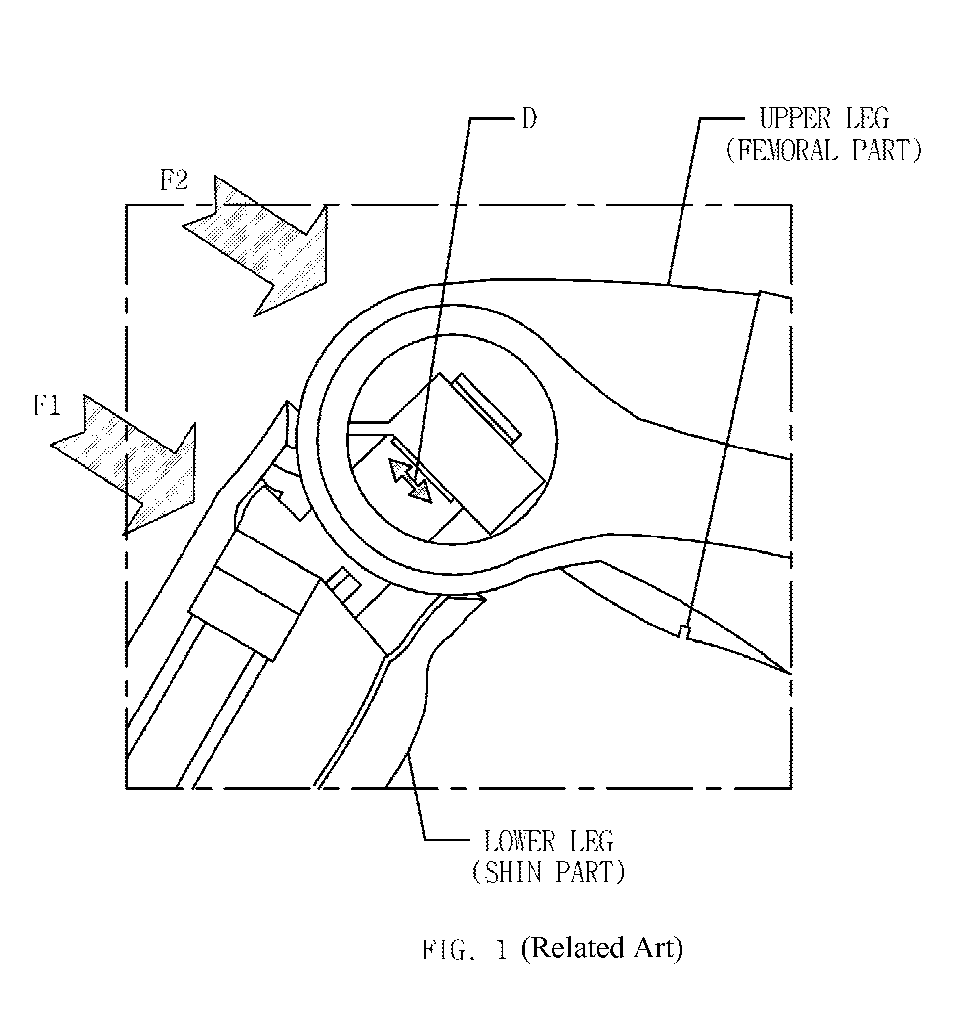
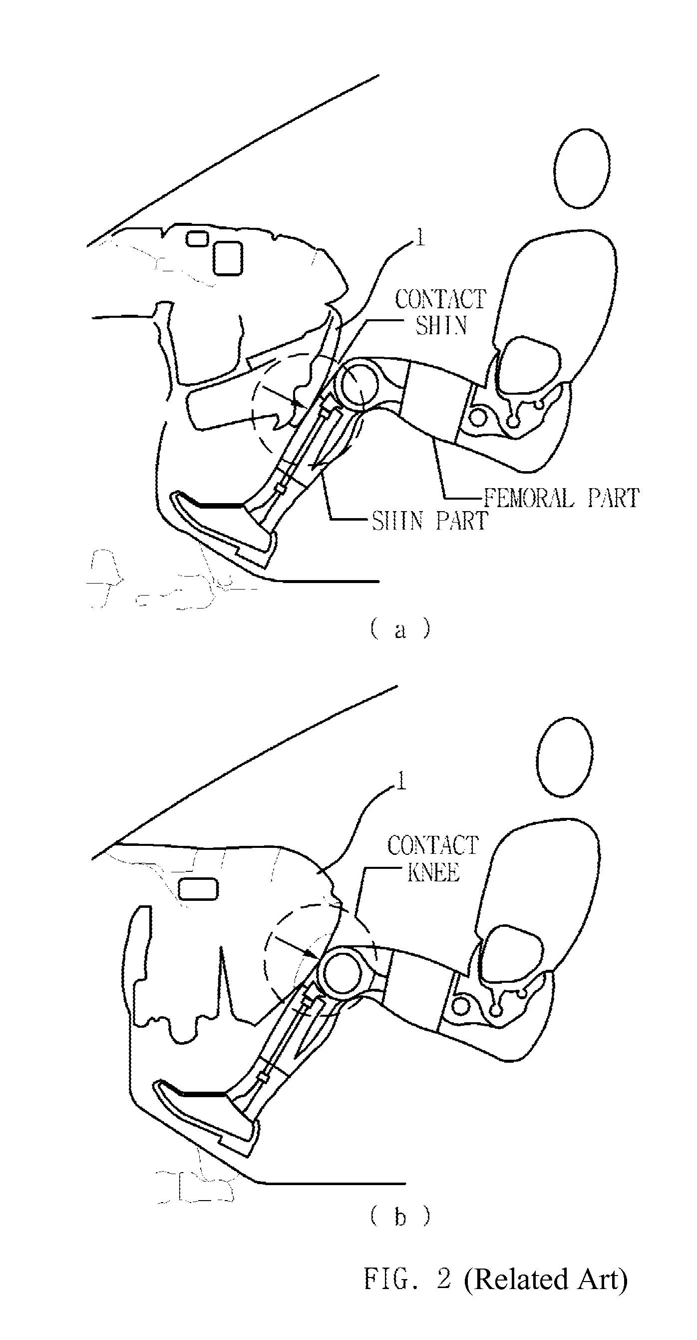
When an initial contact point between the crash pad and the lower extremity of a passenger is located at a lower side thereof upon crash, i.e., when the crash pad collides with the shin part earlier than the knee part of a passenger (initial contact point of the crash pad is located at the shin part), the knee slider may exceed the reference value, causing injuries such as knee dislocation.
However, these have a limitation in reducing the injury of a passenger.
Referring to FIG. 3, when the crash pad 1 first collides with the passenger's shin part upon crash, the femoral part of a passenger relatively moves forward, leading to knee slider of a dummy, particularly, knee dislocation.
However, these methods have limitations due to difficulty in achieving a large improvement effect, excessive change of design, and weakening of the strength of endurance components.
However, this method has an effect only under specific situations, and causes an excessive increase of cost.
Also, this method has an effect only in a case where a space between colliding objects such as knee and crash pad is relatively large.
However, these methods also have a limitation in that the manufacturing cost excessively increases compared to their effects due to the addition of complex components.

Method used


Image

  • Structure for reducing knee injury in vehicle
  • Structure for reducing knee injury in vehicle
  • Structure for reducing knee injury in vehicle

Examples


Embodiment Construction

[0041]Reference will now be made in detail to various embodiments of the present invention(s), examples of which are illustrated in the accompanying drawings and described below. While the invention(s) will be described in conjunction with exemplary embodiments, it will be understood that the present description is not intended to limit the invention(s) to those exemplary embodiments. On the contrary, the invention(s) is / are intended to cover not only the exemplary embodiments, but also various alternatives, modifications, equivalents and other embodiments, which may be included within the spirit and scope of the invention as defined by the appended claims.

[0042]It is understood that the term “vehicle” or “vehicular” or other similar term as used herein is inclusive of motor vehicles in general such as passenger automobiles including sports utility vehicles (SUV), buses, trucks, various commercial vehicles, watercraft including a variety of boats and ships, aircraft, and the like, a...


PUM


Abstract

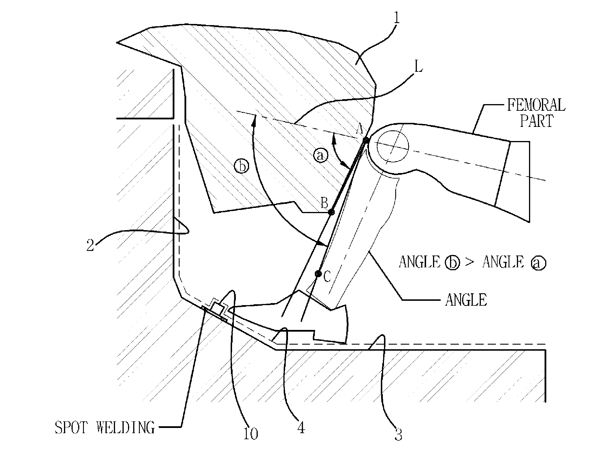
A structure for reducing knee injury in a vehicle, may include a toe stopper disposed on a bottom of a vehicle interior at a driver's seat or a passenger's seat in a traverse direction of a vehicle body, wherein the toe stopper is protrusively disposed from the bottom of the vehicle interior to have a height such that a front tip of a foot of the driver or the passenger is stopped from moving forward and thus a knee part of the driver or the passenger contacts a crash pad earlier than a shin part of the driver or the passenger.

Description

CROSS-REFERENCE TO RELATED APPLICATION[0001]The present application claims priority to Korean Patent Application No. 10-2012-0073114 filed on Jul. 4, 2012, the entire contents of which is incorporated herein for all purposes by this reference.BACKGROUND OF THE INVENTION[0002]1. Field of the Invention[0003]The present invention relates to a structure for reducing knee injury. More particularly, the present invention relates to a structure for effectively reducing knee injury upon crash of vehicles.[0004]2. Description of Related Art[0005]Generally, a variety of safety apparatuses and safety structures are being applied to vehicles to safely protect passengers and minimize the degree of injury upon crash.[0006]Since the safety apparatuses and safety structures are important components that are directly associated with passengers' lives, the safety apparatuses and safety structures need to be designed to satisfy a certain level of performance. Vehicle manufacturers are designing the ve...

Claims


Application Information

Patent Timeline
IPC IPC(8): B60R21/02
CPCB60R21/02B60R2021/0053B60R2021/0213B60R21/206B62D25/20
Inventor AHN, BYENG JIK
Owner HYUNDAI MOTOR CO LTD
Learn More