

Display device and control method therefor
- Summary
- Abstract
- Description
- Claims
- Application Information
AI Technical Summary
Benefits of technology
Problems solved by technology
Method used
Image

Examples
first embodiment
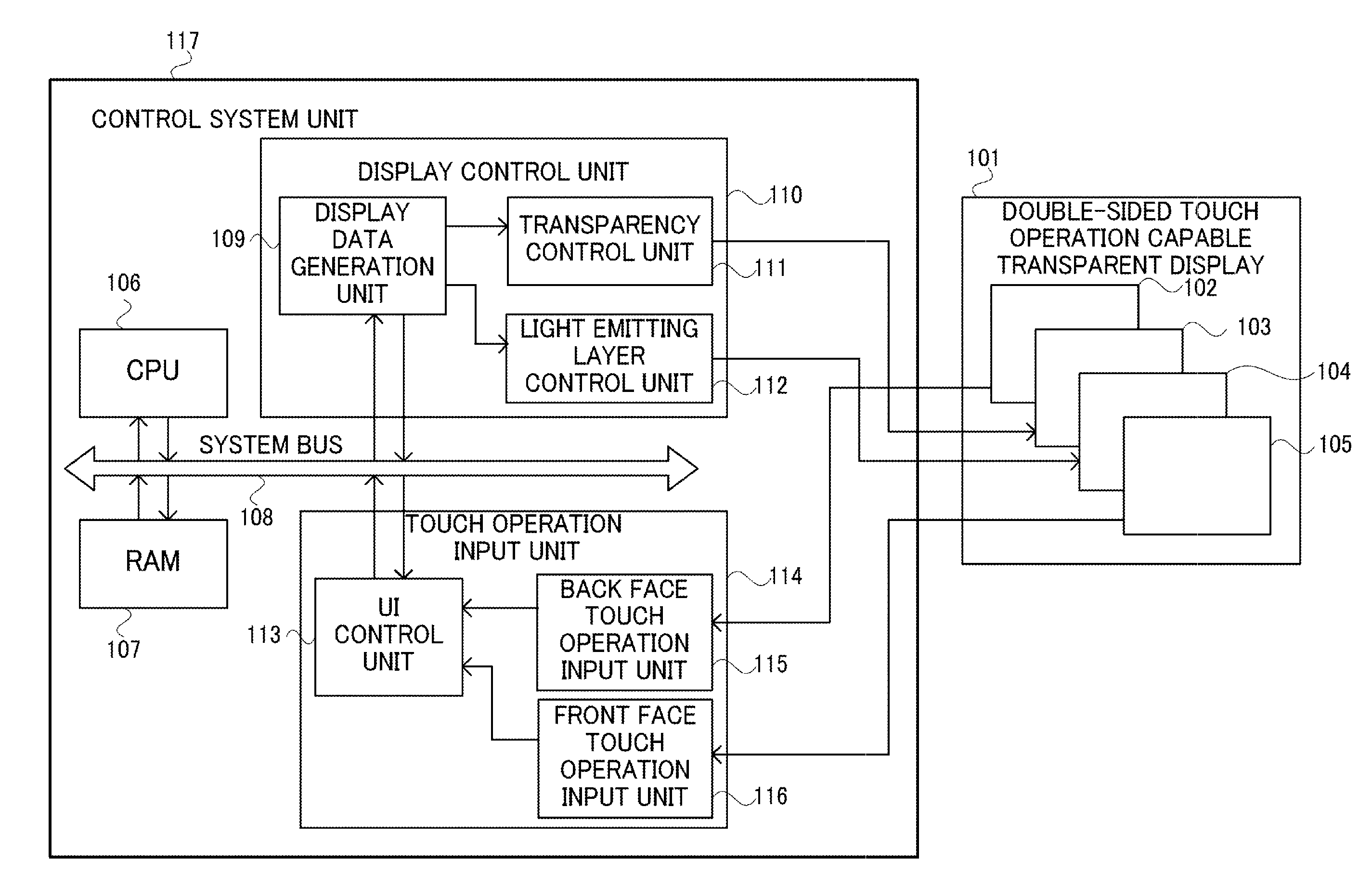
[0062]FIG. 1 is a block diagram of a display device for a portable terminal or a personal digital assistant which is one embodiment of the present invention. The display device of this embodiment is composed of a transparent display 101 compatible with double-sided touch operation and a control system unit 117.
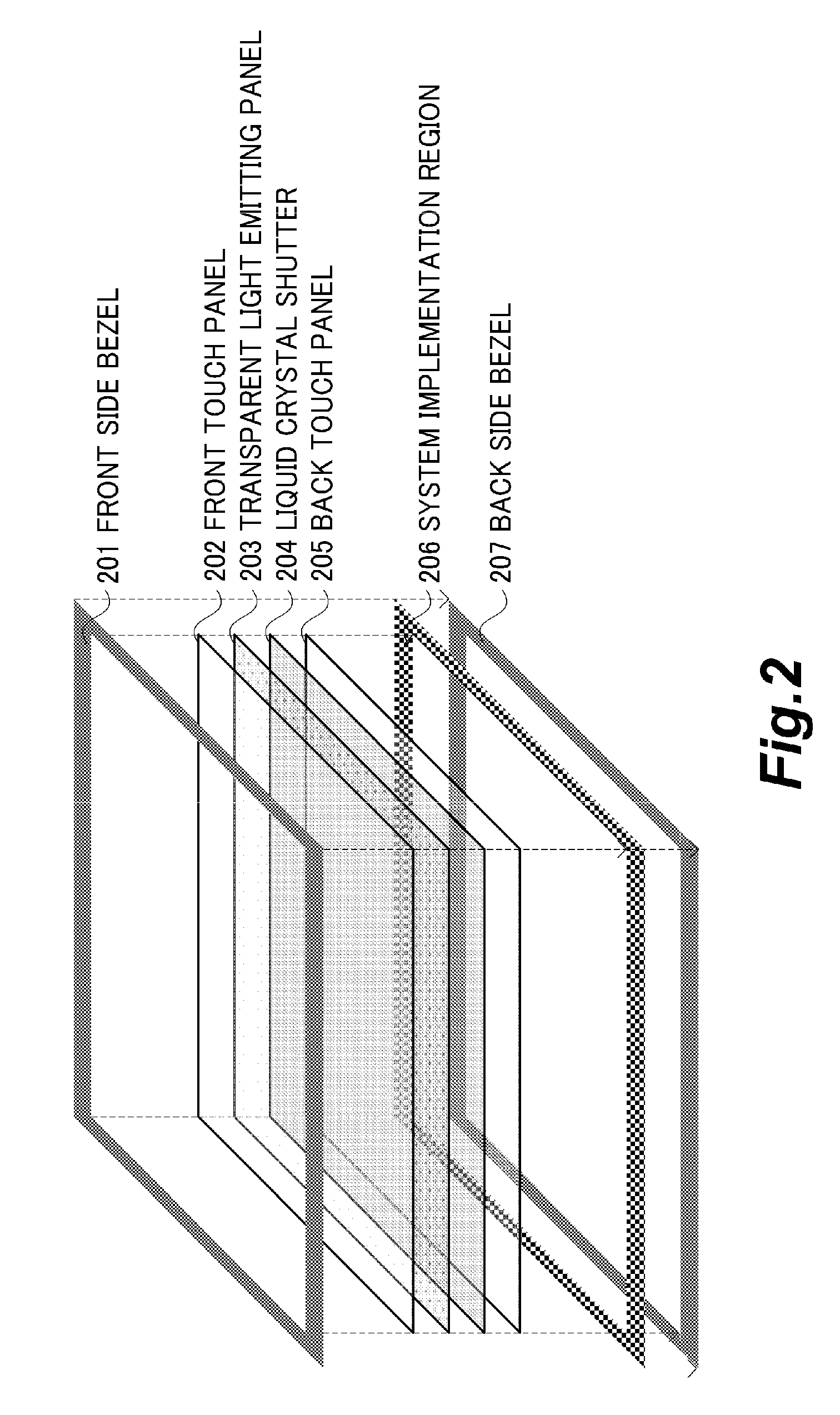
[0063]The transparent display 101 is a transparent display panel in which a touch operation can be carried out from the opposite surfaces thereof, i.e., a front face and a back face. The transparent display 101 is composed of a back touch panel 102, a liquid crystal shutter 103, a transparent light emitting panel 104, and a front touch panel 105.
[0064]The front touch panel 105 has a touch sensor provided on its transparent panel surface for detecting a touch operation from the front face of the portable terminal. Detection of the touch operation is carried out by detecting that a user contacted a screen, and by detecting the coordinate position of a contact point on the screen...
second embodiment
[0096]Reference will be made to the operation of a display device in this second embodiment by using examples of a display screen and an operation image shown in FIG. 5A through FIG. 5D. The construction and implementation form of a portable terminal having a transparent display are the same as those in FIG. 1 and FIG. 2.
[0097]FIG. 5A shows a state in which a user holds a transparent display portable terminal 501 in the form of clamping it with a thumb and an index finger. A display object 502 is in a two-dimensional plane from a display point of view, but as data inside the terminal, it is composed of three-dimensional data. That is, it is assumed that the display object 502 has data in x, y and z directions, respectively, so that it can be displayed in a state of being rotated in a virtual three-dimensional space by means of user's operations. At this time, a front face touch sliding direction 504 indicates an operation to slide upward in a state where the front face is touched wi...
third embodiment
[0109]Now, reference will be made to the operation of a display device in this third embodiment by using examples of a display screen and an operation image which are shown in FIG. 7A and FIG. 7B. The construction and implementation form of a portable terminal having a transparent display are the same as those in FIG. 1 and FIG. 2.
[0110]FIG. 7A is a view showing a case where a transparent display portable terminal 701 is in a sleep state in which it does not receive touch operations in order to prevent malfunction and to reduce power consumption. It is preferable that the sleep state be released only by carrying out a special operation.
[0111]In this embodiment, reference will be made to the display device which is constructed such that it is released from a sleep state, only when touch operations are carried out at the same time with respect to a wake up menu 702 from opposite sides of a screen, i.e., a back face and a front face. The wake up menu 702 is a third component which is a...
PUM
 Abstract
Description
Claims
Application Information