Directional indicator and straddle type vehicle directional indicator system including the same

a technology of directional indicators and straddle-type vehicles, which is applied in the direction of electroluminescent light sources, transportation and packaging, electric lighting sources, etc., can solve the problems of unsuitable for determining, the amount of light of the directional indicator cannot be correctly determined, and the inability to accurately determine the amount of light, etc., to achieve the effect of convenient detection

Active Publication Date: 2014-01-16
YAMAHA MOTOR CO LTD
View PDF8 Cites 9 Cited by
  • Summary
  • Abstract
  • Description
  • Claims
  • Application Information

AI Technical Summary

Benefits of technology

[0011]In an arrangement including LED series circuits connected in parallel, where each LED series circuit has a plurality of LEDs connected in series, the current in the plurality of LED series circuits may be measured to detect a failure in the LED series circuits more correctly. Thus, a failure in the LED series circuits may be easily detected.

Problems solved by technology

However, the arrangement of JP 2004-9825 A is not suitable for determining the number of LEDs that failed since it measures the entire amount of current in the light emitter.
This means that the amount of light of the directional indicator cannot be correctly determined.
Thus, the arrangement of JP 2004-9825 A is not suitable for determining whether the directional indicator is emitting a sufficient amount of light.
This means that, if the voltage applied to the directional indicator decreases, changes in the amount of current measured when an LED fails are small, as well.
In such cases, the arrangement of JP 2004-9825 A is not suitable for detecting a failure of an LED since changes in the entire amount of current when an LED fails are small.
Thus, a failure in the LED series circuits may be easily detected.

Method used


Image

  • Directional indicator and straddle type vehicle directional indicator system including the same
  • Directional indicator and straddle type vehicle directional indicator system including the same
  • Directional indicator and straddle type vehicle directional indicator system including the same

Examples


Embodiment Construction

[0017]Embodiments will be described with reference to the drawings. The sizes of the components in the drawings do not exactly represent the sizes of the actual components and the size ratios or the like of the components.

[0018]In the following description, the directions “front / forward”, “rear(ward)”, “left” and “right” mean directions as perceived by a rider sitting on the seat 6 of the motorcycle 1 and grasping the handlebars 5.

[0019]

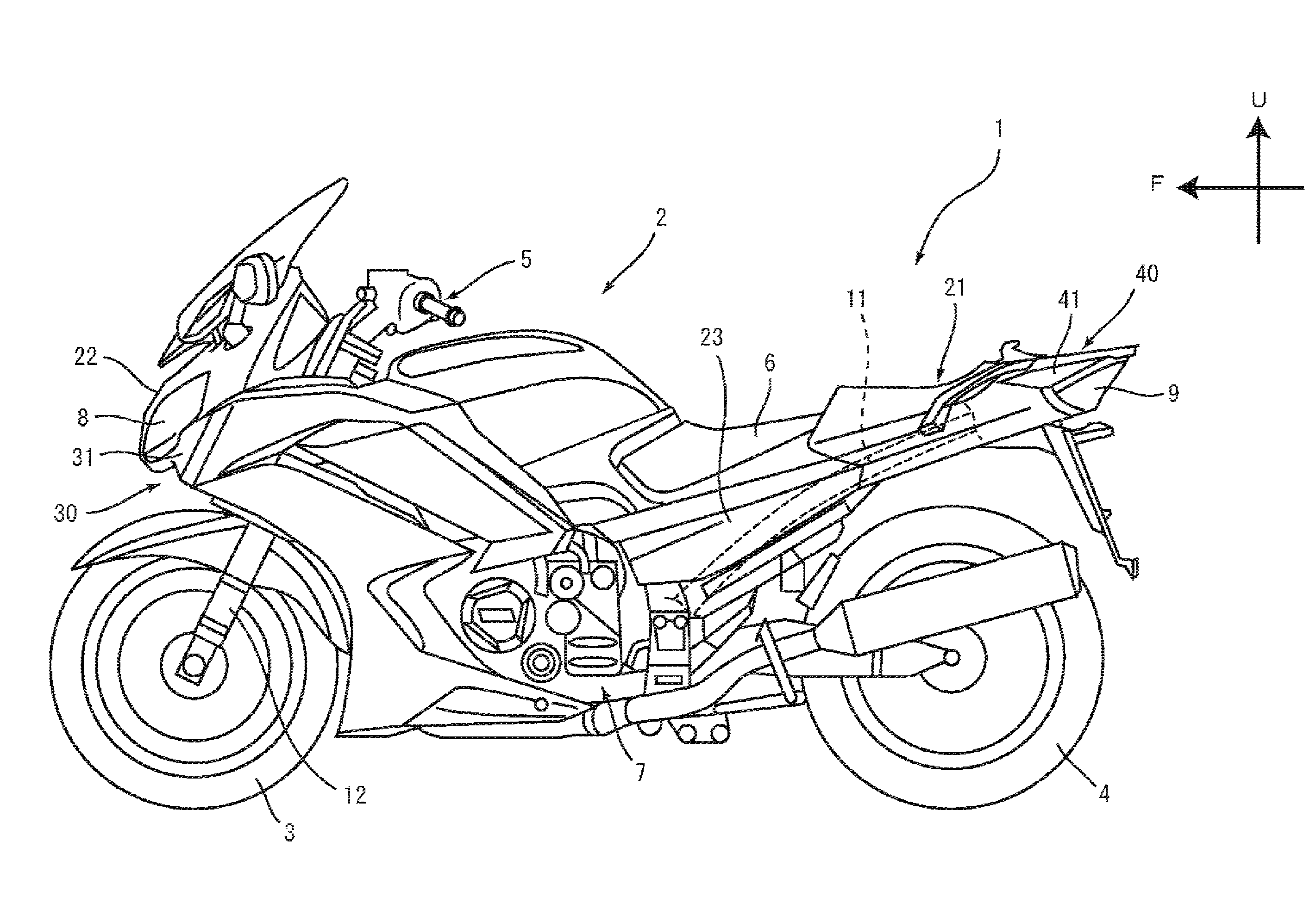
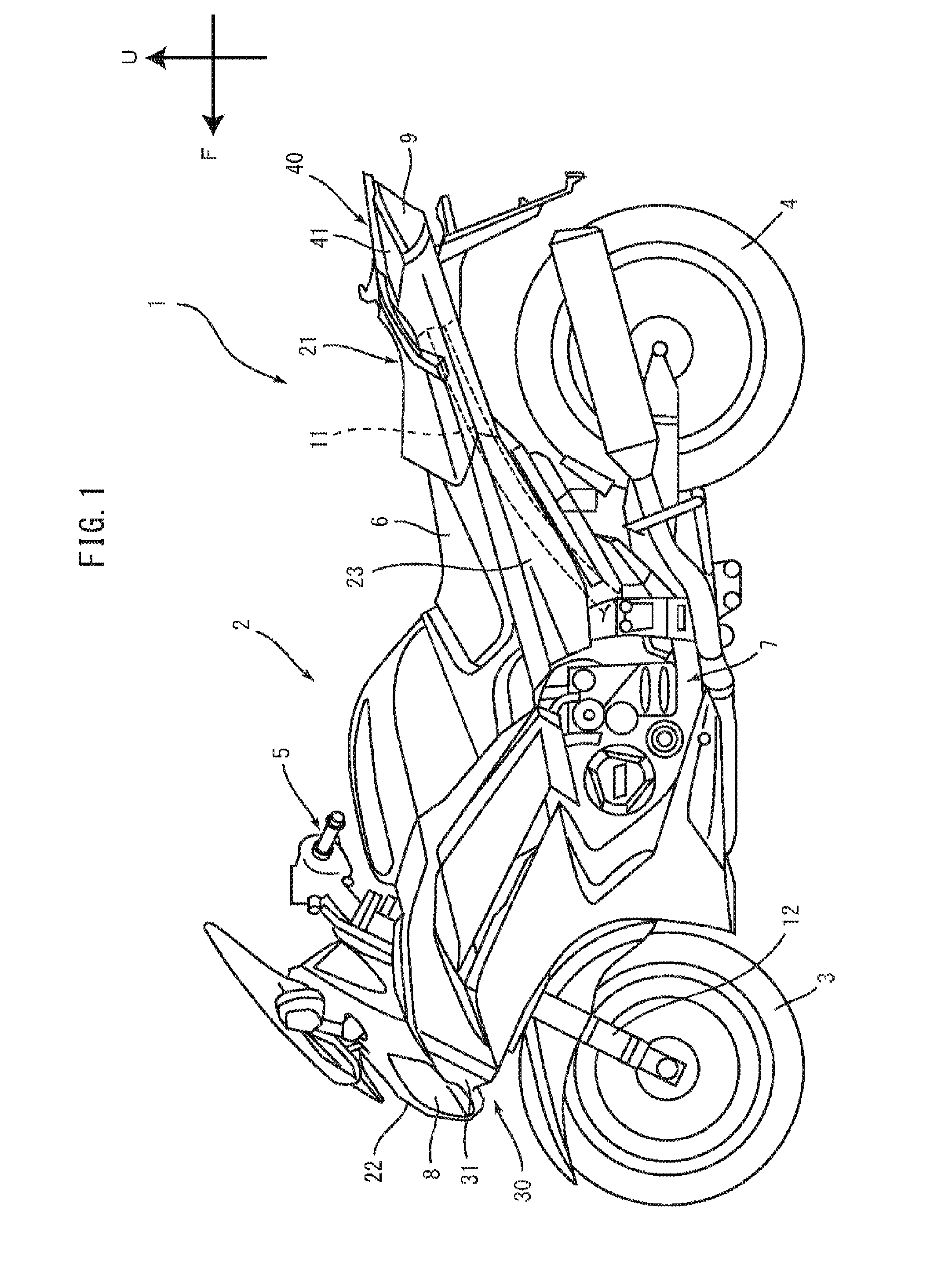
[0020]FIG. 1 is a left side view of an entire motorcycle 1 (straddle type vehicle) according to an embodiment of the present invention. The motorcycle 1 includes a vehicle body 2, a front wheel 3 located forward of the vehicle body 2, and a rear wheel 4 located rearward of the vehicle body 2. Arrow “F” in FIG. 1 indicates the forward direction with respect to the motorcycle 1, and arrow “U” indicates the upward direction with respect to the motorcycle 1.

[0021]The vehicle body 2 includes a body frame 11, a body cover 21, handlebars 5, a seat 6, and a ...


PUM


Abstract

A directional indicator system includes a directional indicator that includes a plurality of LED series circuits each connected in parallel to another of the LED series circuits. Each LED series circuit includes LEDs connected in series. A driver is configured to control driving of the directional indicator. The driver includes LED drivers that are each configured to drive a corresponding one of the LED series circuits. The driver also includes a plurality of current detectors that are each configured to measure a value of a current in a corresponding one of the LED series circuits.

Description

CROSS-REFERENCE TO RELATED APPLICATION[0001]This application is based on, and claims priority to, Japanese Patent Application No. 2012-156133, filed on Jul. 12, 2012 the contents of which are incorporated herein by reference.BACKGROUND[0002]1. Technical Field[0003]The present invention relates to a directional indicator for a straddle type vehicle and a directional indicator system including the same.[0004]2. Description of the Background Art[0005]As disclosed in JP 2004-9825 A, a vehicle lamp fitting including a plurality of light-emitting diodes (LEDs) is known. Such a vehicle lamp fitting includes a light emitter having a plurality of light emitting units connected in parallel, each light emitting unit having two LEDs connected in series.[0006]The above vehicle lamp fitting uses one power source to control the power supply to the plurality of light emitting units. The vehicle lamp fitting further include a single break detecting means for the plurality of light emitting units. Mo...

Claims


Application Information

Patent Timeline
Patent Type & Authority Applications(United States)
IPC IPC(8): B60Q1/34H05B44/00
CPCB60Q1/34B60Q11/007B60Q1/0088H05B45/54H05B45/52H05B45/46H05B45/48
Inventor YAMAGUCHI, TAKAO
Owner YAMAHA MOTOR CO LTD
Why Eureka
Try Eureka