Dispensing vial

Inactive Publication Date: 2014-01-16
LEVINE JONATHAN B
View PDF4 Cites 6 Cited by
  • Summary
  • Abstract
  • Description
  • Claims
  • Application Information

AI Technical Summary

Benefits of technology

The present invention provides a vial with a piercing element that can pierce a foil seal on the container. This allows for easy opening of the container and access to the contents. The cap has a limit stop element that needs to be removed to activate the piercing element. Once the limit stop element is removed, the piercing element can pierce the foil seal on the container to create a secure and tight seal.

Problems solved by technology

However, the cap may not be reciprocated downwardly to cause the piercing element to pierce the foil seal until the limit stop element is removed.

Method used


Image

  • Dispensing vial
  • Dispensing vial
  • Dispensing vial

Examples


Embodiment Construction

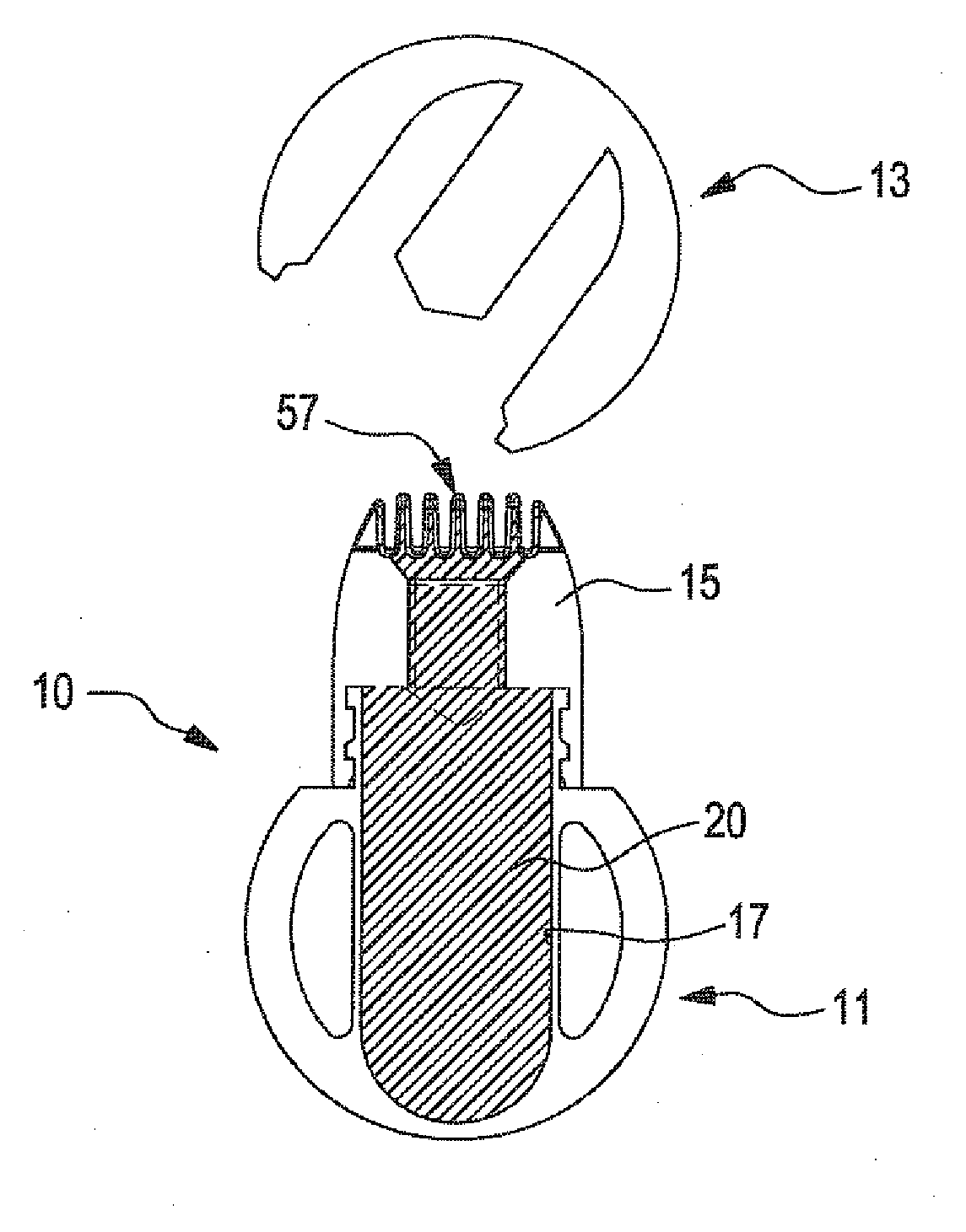
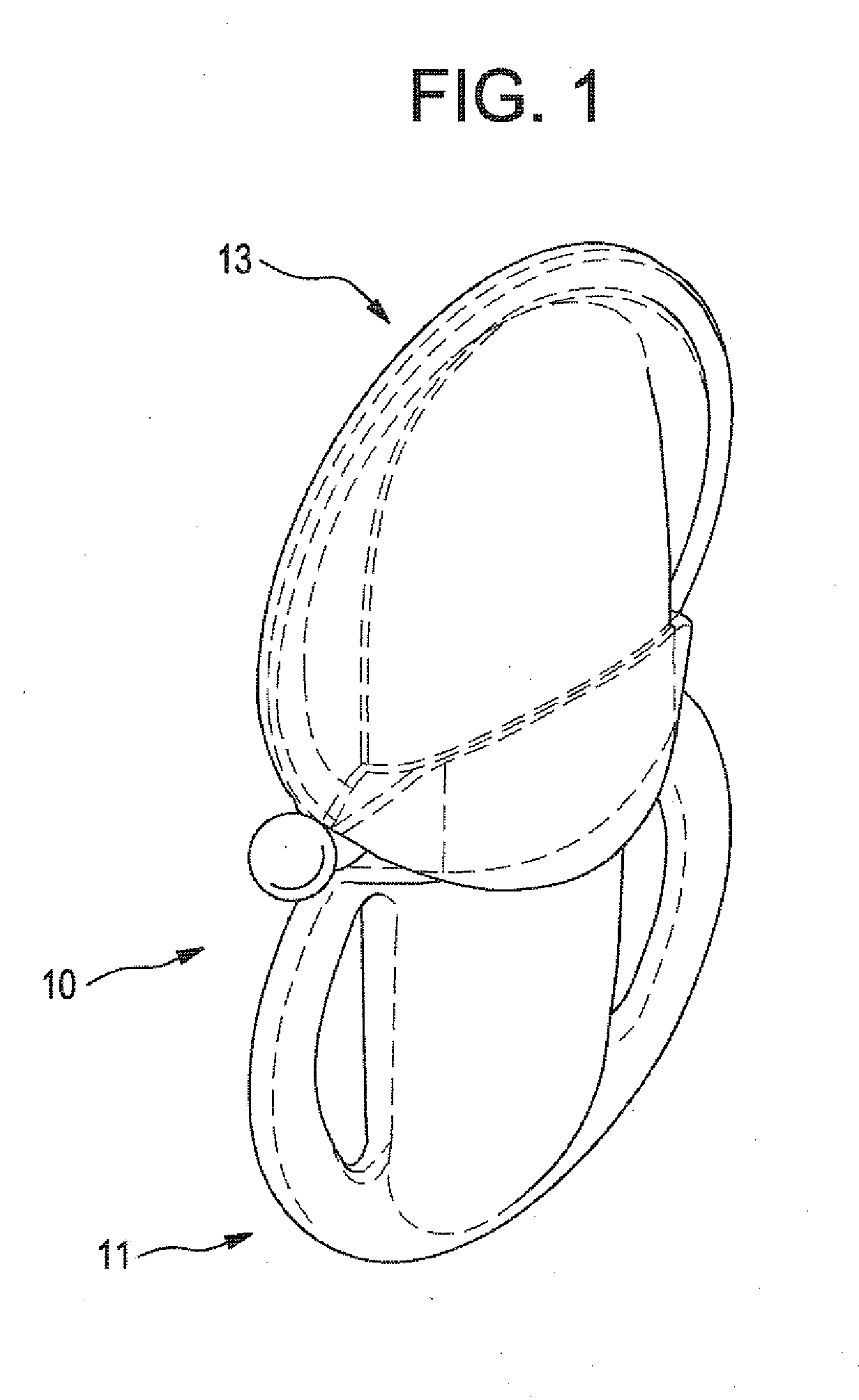
[0040]With reference to FIG. 1, the present invention is generally designated by the reference numeral 10 and includes a container 11, a cap 13, and an applicator member better seen with reference to FIGS. 12-15 and generally designated by the reference numeral 15.

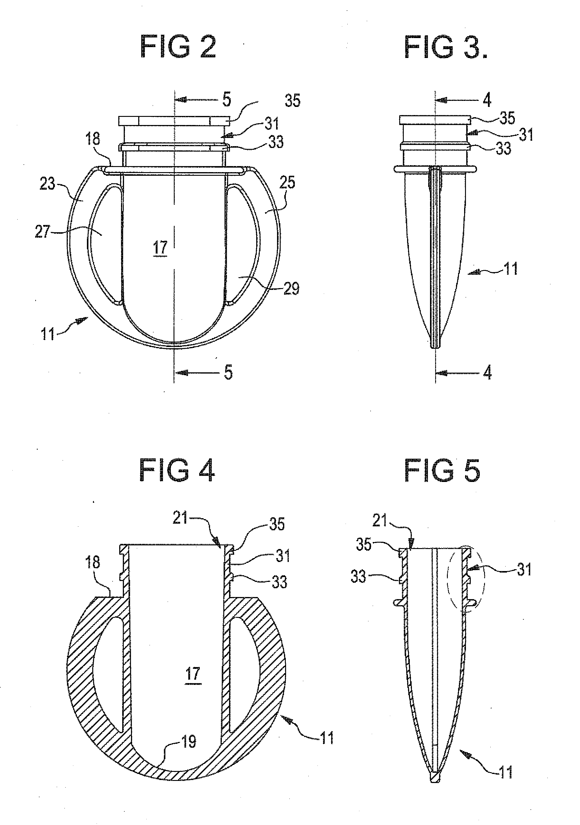
[0041]With reference to FIGS. 2-5, the container 11 includes a central chamber 17 that has a closed bottom 19 and an upwardly facing opening 21. The chamber 17 is designed to receive a quantity of a substance to be dispensed from the container 11. That substance may comprise a tooth whitening gel, paste or liquid, a substance for treating bacteria in the oral cavity, or any other liquid, gel or paste. As seen in FIG. 2, the container 11 has gripping handles 23 and 25 that are arcuate in nature and define openings 27 and 29 between the handles 23 and 25, respectively, and the chamber 17.

[0042]As seen in particular in FIGS. 2 and 5, the opening 21 is defined at the top of a neck 31 that has a pair of annular protrusions 33 a...


PUM


Abstract

A container has a sealed chamber. An applicator mounted on the container has a passageway and a comb-like applicator having a central opening that allows flow of a gel through its plural teeth. A cap is mounted over the applicator member and carries a piercing element. A limit stop limits the downward movement of the cap. The limit stop is attached to the applicator member by a frangible coupling. The limit stop can be broken off the applicator, whereupon the cap may be pushed downward so the piercing element pierces the foil seal. Thereafter, the flexible container may be squeezed to dispense the gel. The tip of the applicator is designed to target the gel to the teeth, avoiding the lips and the gums and avoiding irritation and preventing contact with sensitive areas.

Description

BACKGROUND OF THE INVENTION[0001]The present invention relates to a dispensing vial. The preferred environment of use of the present invention is in the dispensing of tooth whitening substances on the teeth of a user. However, the inventive vial may also be used in any other environment in which a substance must be stored in a hermetically sealed environment and dispensed when desired in an accurate and efficient manner.[0002]Applicant is also the inventor in Published Application Nos. US 2010 / 0240013, published Sep. 23, 2010, and US 2011 / 0183296, published Jul. 28, 2011. These published applications disclose dispensing devices including a container in which a substance is stored, a cap sealing the container, and structure permitting removal of the cap to dispense the substance within the container. In each of these earlier published applications, the cap includes structure providing the sealing function. The present invention differs from the teachings of these earlier published ap...

Claims


Application Information

Patent Timeline
IPC IPC(8): A61C17/00B05C17/005
CPCA61C19/02A61C19/066A61C2202/00
Inventor LEVINE, JONATHAN B.
Owner LEVINE JONATHAN B
Why Eureka
Try Eureka