High-reflection submount for light-emitting diode package and fabrication method thereof

a technology of light-emitting diodes and silicon submounts, which is applied in the direction of lasers, semiconductor lasers, basic electric elements, etc., can solve the problems of low production cost, high heat generation, and low reliability of leds,

Active Publication Date: 2014-01-16
XINTEC INC
View PDF0 Cites 3 Cited by
  • Summary
  • Abstract
  • Description
  • Claims
  • Application Information

AI Technical Summary

Benefits of technology

The present invention provides an improved method for fabricating a high-reflection silicon submount for LED packaging. This method involves preparing a silicon substrate, forming a reflection layer on the substrate, etching the substrate to create openings, depositing an insulating layer to cover the reflection layer and substrate, adding a seed layer, creating a resist pattern, etching the seed layer, adding a metal layer, and electroplating a metal layer to create the submount. The resulting submount has improved reflection of light and better electrical performance. The invention also provides an LED package that includes the silicon submount and an LED die mounted on it. The technical effects of this invention include improved performance and reliability of LED packaging.

Problems solved by technology

In order to achieve the high lumens output and flux density, the LEDs must be driven at high current levels, which in turn results in high levels of heat generation.
However, the conventional ceramic submount or substrate material for LED packaging has unsatisfactory heat dissipating efficiency, hence leading to reliability issue and decrease of LED's lifetime.
In addition to the heat dissipation issue, the LED manufacturers are also facing problems such as relatively high production cost and inadequate illumination efficiency.

Method used


Image

  • High-reflection submount for light-emitting diode package and fabrication method thereof
  • High-reflection submount for light-emitting diode package and fabrication method thereof
  • High-reflection submount for light-emitting diode package and fabrication method thereof

Examples


Embodiment Construction

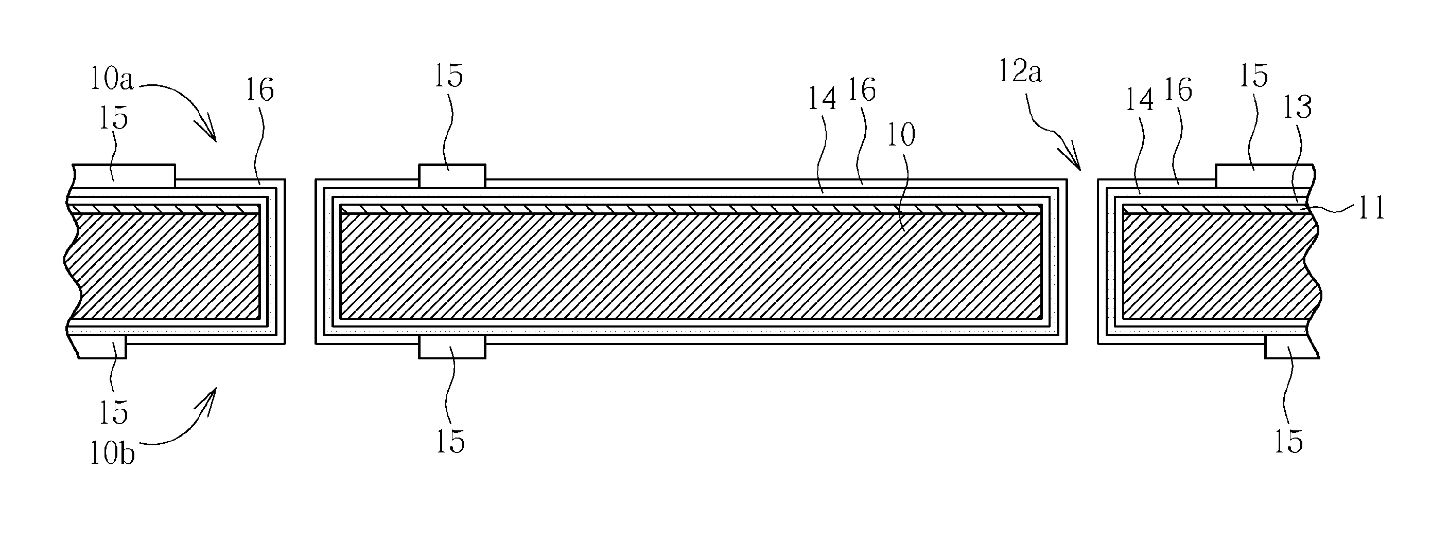
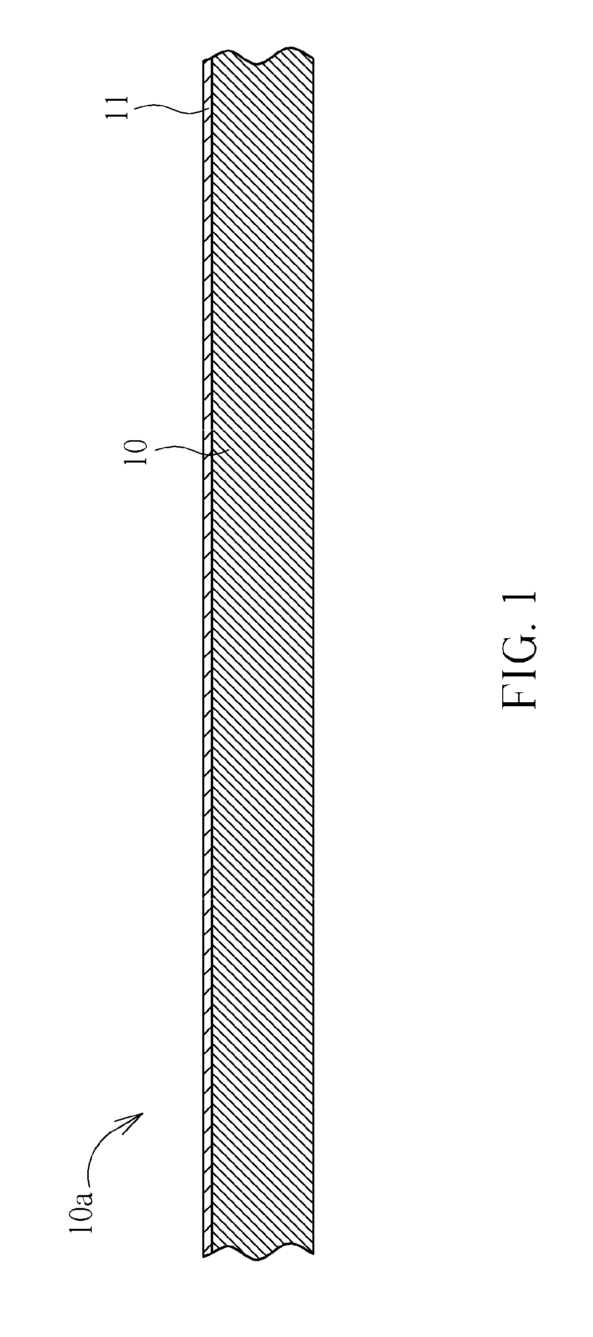
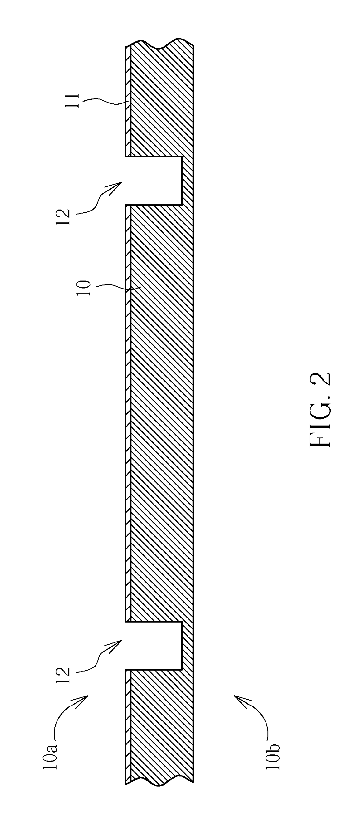
[0017]The invention pertains to a method of fabricating a silicon submount for light emitting device package, which can be incorporated into the wafer level chip scale package (WLCSP) processes. In one embodiment, the light emitting device package structure may be fabricated using a WLCSP process to package a light emitting device, for example, a light emitted diode (LED) or laser diode (LD). The wafer level chip scale package process mentioned above mainly means that after the package process is accomplished during the wafer stage, the wafer with chips is cut to obtain separate independent packages.

[0018]However, in an embodiment of the invention, separate independent chips may be redistributed overlying a supporting wafer serving as a carrier and then be packaged, which may also be referred to as a wafer scale package process. In addition, the above mentioned wafer scale package process may also be adapted to form electronic device packages of multi-layer integrated circuit device...


PUM

PropertyMeasurementUnit
releasing energyaaaaaaaaaa
energy consumptionaaaaaaaaaa
lifetimeaaaaaaaaaa

Abstract

A method for fabricating a silicon submount for LED packaging. A silicon substrate is provided. A reflection layer is formed on the silicon substrate. Portions of the reflection layer and the silicon substrate are removed to form openings. A wafer backside grinding process is carried out to thin the silicon substrate thereby turning the openings into through silicon vias. An insulating layer is then deposited to cover the reflection layer and the silicon substrate. A seed layer is formed on the insulating layer. A resist pattern is then formed on the seed layer. A metal layer is formed on the seed layer not covered by the resist pattern. The resist pattern is then stripped. The seed layer not covered by the metal layer is then removed.

Description

CROSS REFERENCE TO RELATED APPLICATIONS [0001]This application claims the priority from U.S. provisional application No. 61 / 303,683 filed Feb. 12, 2010.BACKGROUND OF THE INVENTION[0002]1. Field of the Invention[0003]The present invention relates generally to light-emitting diode packaging. More particularly, the present invention relates to high-reflection silicon submounts for light-emitting diode packaging and fabrication method thereof.[0004]2. Description of the Prior Art[0005]As known in the art, a light-emitting diode (LED) is a semiconductor light source. LEDs are used as indicator lamps in many devices, and are increasingly used for lighting. When a light-emitting diode is forward biased (switched on), electrons are able to recombine with holes within the device, releasing energy in the form of photons. LEDs present many advantages over incandescent light sources including lower energy consumption, longer lifetime, improved robustness, smaller size, faster switching, and gre...

Claims


Application Information

Patent Timeline
Patent Type & Authority Applications(United States)
IPC IPC(8): H01L33/60H01S5/023
CPCH01L33/60H01L21/486H01L23/147H01L23/49827H01L33/44H01L33/486H01L33/62H01L33/641H01L2933/0033H01L2224/73265H01S5/023H01S5/0233H01S5/0235H01L2224/48091H01L2924/00014
Inventor WU, SHANG-YICHEN, CHIEN-HUI
Owner XINTEC INC
Why Eureka
Try Eureka