Anti-Sticking Electrosurgical Instrument

an electrosurgical instrument and anti-stick technology, applied in the field of electrosurgical instruments, can solve the problems of repeat bleeding, etc., and achieve the effect of preventing the expansion of the wound, extending the surgery time, and affecting the success rate of surgery

Inactive Publication Date: 2014-01-16
ADVANCED MEDICAL DESIGN
View PDF2 Cites 4 Cited by
  • Summary
  • Abstract
  • Description
  • Claims
  • Application Information

AI Technical Summary

Benefits of technology

The present invention provides an anti-sticking electrosurgical instrument that prevents the instrument from sticking to the targeted areas during surgery. This is achieved by coating the instrument surface with an anti-sticking layer that prevents wound expansion, bleeding, and increases the conductivity and resistance to clean, which prevents sticking after long-term use.

Problems solved by technology

The technical problem addressed in this patent text is the sticking and poor conductivity of conventional electrosurgical instruments used in minimally invasive surgery, which can cause complications such as bleeding, extended surgery time, and poor surgical outcomes. The inventor has developed an anti-sticking electrosurgical instrument to overcome this problem.

Method used


Image

  • Anti-Sticking Electrosurgical Instrument
  • Anti-Sticking Electrosurgical Instrument
  • Anti-Sticking Electrosurgical Instrument

Examples


Embodiment Construction

[0021]To more clearly describe an anti-sticking electrosurgical instrument according to the present invention, embodiments of the present invention will be described in detail with reference to the attached drawings hereinafter:

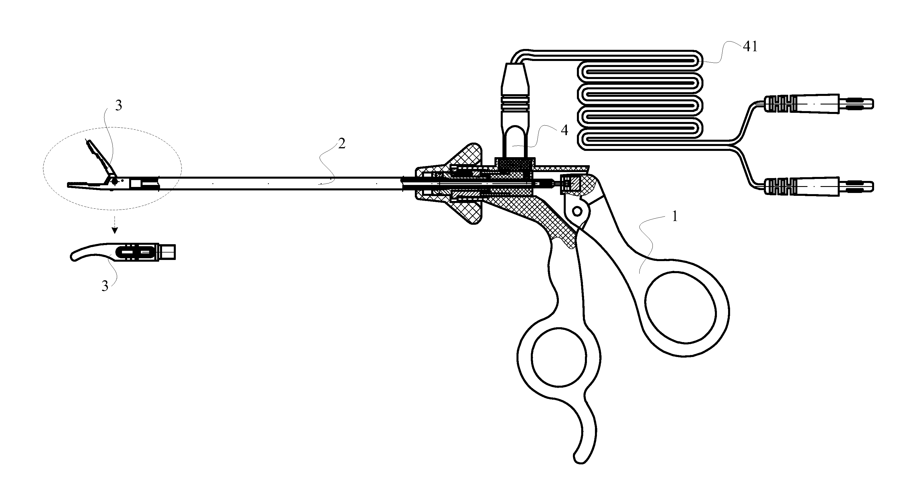
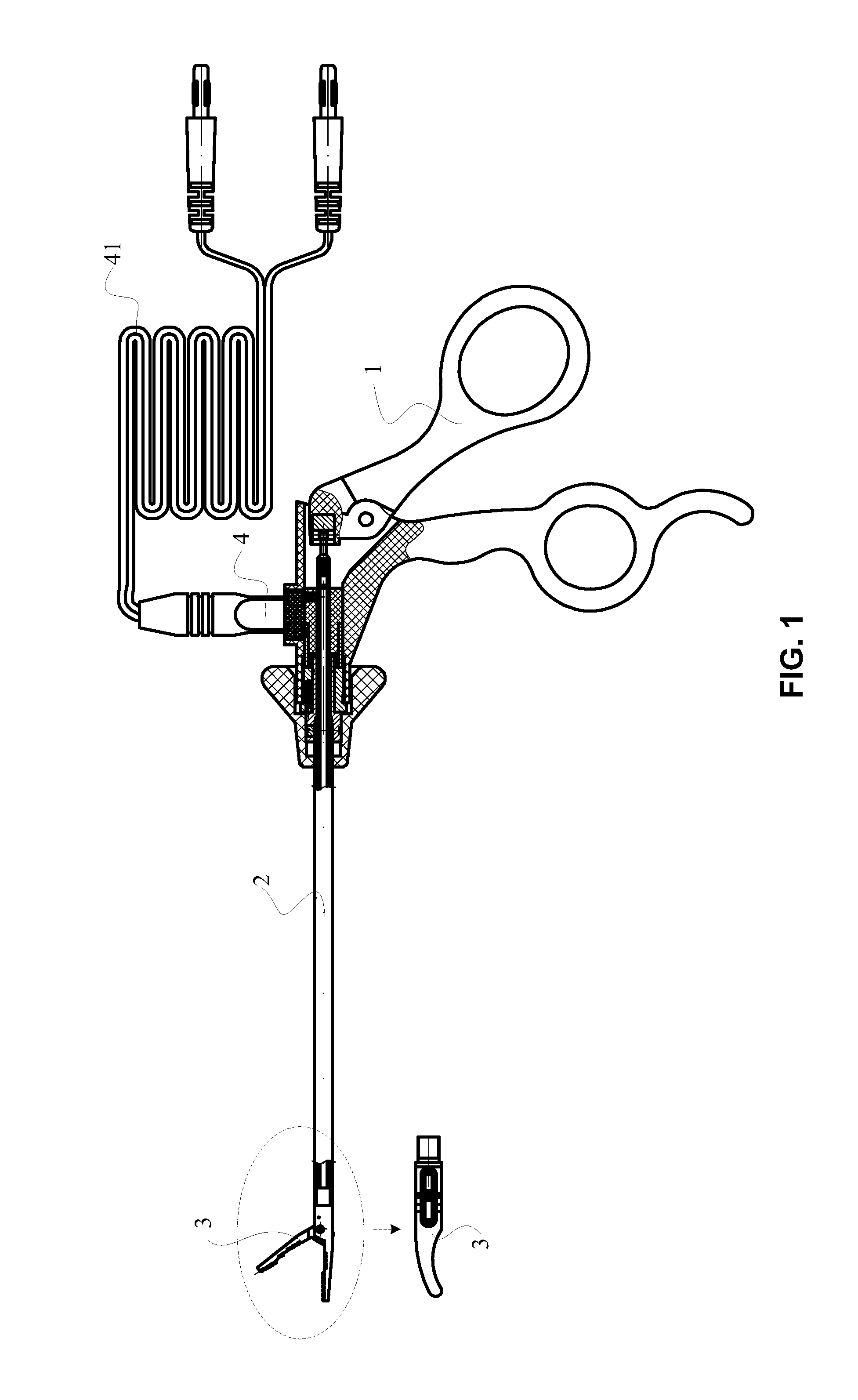
[0022]With reference to FIG. 1, there is shown an appearance view of a first embodiment for the anti-sticking electrosurgical instrument according to the present invention. As shown in FIG. 1, the anti-sticking electrosurgical instrument includes: a handle portion 1, an isolation tube 2, an instrument portion 3, and an electrode 4, wherein the isolation tube 2 is connected to the handle portion 1 by one end thereof, and the instrument portion 3 is connected to another end of the isolation tube 2 and provided with an anti-sticking layer is formed on the surface thereof. In anti-sticking electrosurgical instrument, the instrument portion 3 can be driven by the handle portion 1 via the isolation tube 2; In addition, in the first embodiment of the instrument port...


PUM

PropertyMeasurementUnit
Thicknessaaaaaaaaaa
Water contact angleaaaaaaaaaa
Adhesion strengthaaaaaaaaaa

Abstract

The present invention relates to a non-stick coated electrosurgical diathermy instrumentation, comprising: a handle portion; an isolation tube, connected to the handle portion by one end thereof; an instrument portion, connected to another end of the isolation tube, wherein an anti-sticking layer is formed on the surface of the instrument portion; and an electrode, connected to the handle portion and an external conductive member. In the present invention, the instrument portion is able to generate heat when the conductive member conducts electricity to the instrument portion.

Description


Claims


Application Information

Patent Timeline
Owner ADVANCED MEDICAL DESIGN
Why Eureka
Try Eureka