Swivel support structure

Active Publication Date: 2014-01-23
GRIDLEY WILLIAM E
View PDF14 Cites 9 Cited by
  • Summary
  • Abstract
  • Description
  • Claims
  • Application Information

AI Technical Summary

Benefits of technology

The present invention aims to improve the support system for ventilators by using curved ventilator plates that better match a cover. Additionally, the invention includes a swivel interface that can securely connect to a support surface. These improvements enhance the stability and efficiency of the ventilator system.

Problems solved by technology

One problem with using a porous or non porous cover to protect a vehicle is moisture and mildew resulting from condensation and other sources of moisture.
In a very real sense, the trapped moisture is more damaging than the vehicle being left uncovered.
An uncovered vehicle can dry out, but a covered vehicle with moisture trapped therewithin does not dry out and the vehicle is constantly exposed to the moisture which over a shortened period of time can cause a significant amount of damage.
Even with the breathable materials, moisture remains trapped inside the cover for a longer period of time than it would if the cover were removed and the vehicle allowed to air dry.
Indeed, indoor storage, for example, where the air is not conditioned or otherwise dry, can experience high humidity.
In such an environment, the moist air can damage a covered object or vehicle by becoming trapped under the cover.

Method used


Image

  • Swivel support structure
  • Swivel support structure
  • Swivel support structure

Examples


Embodiment Construction

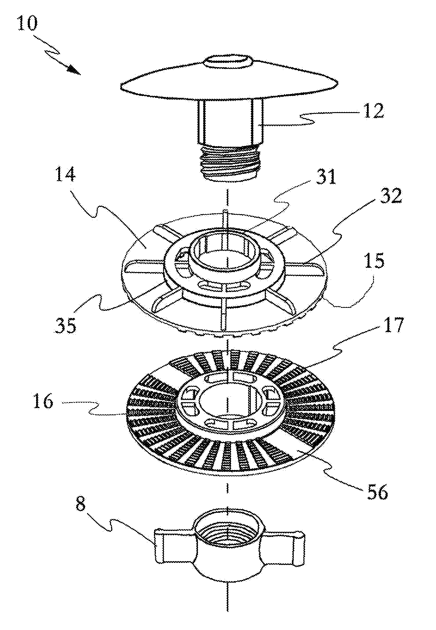
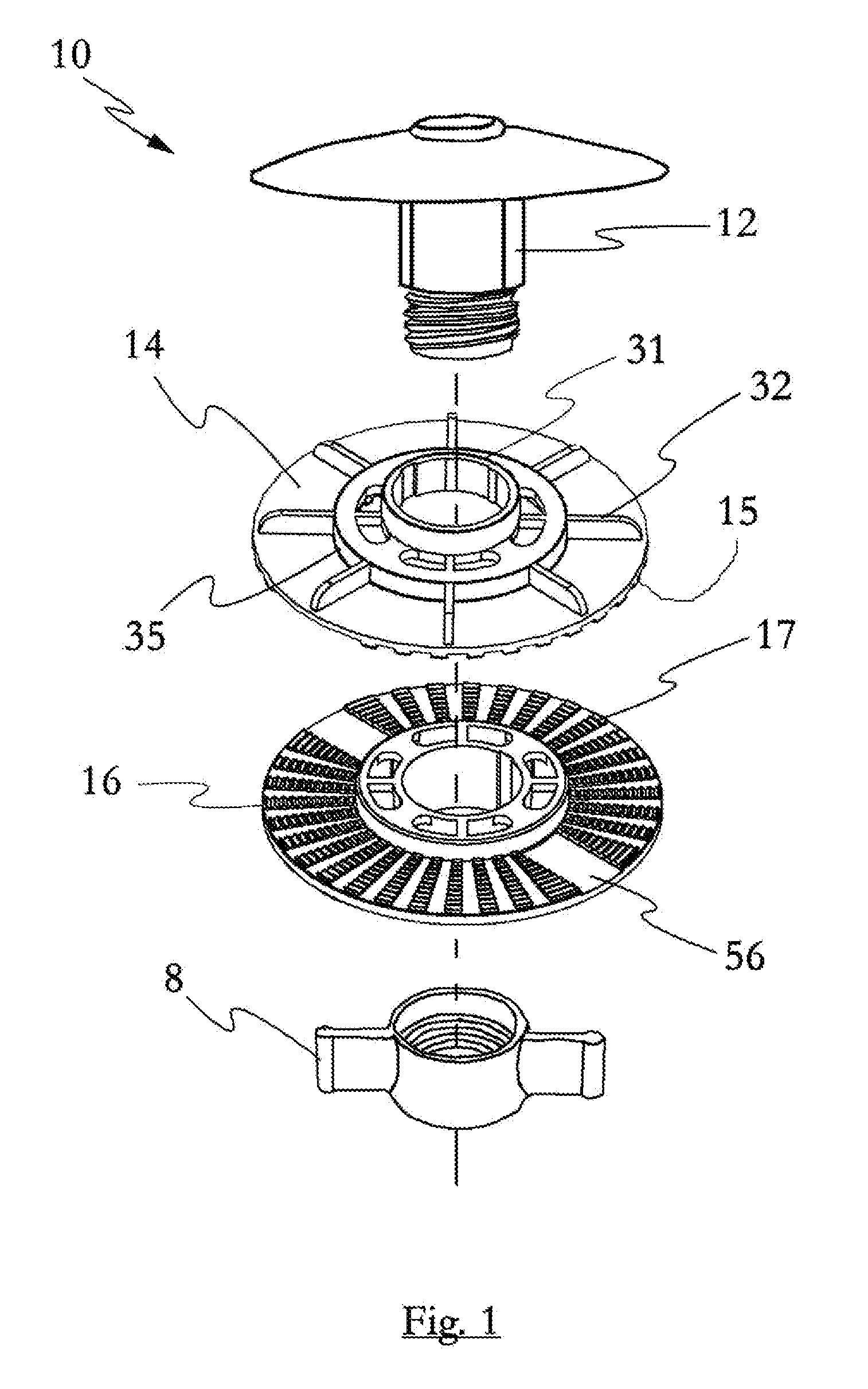
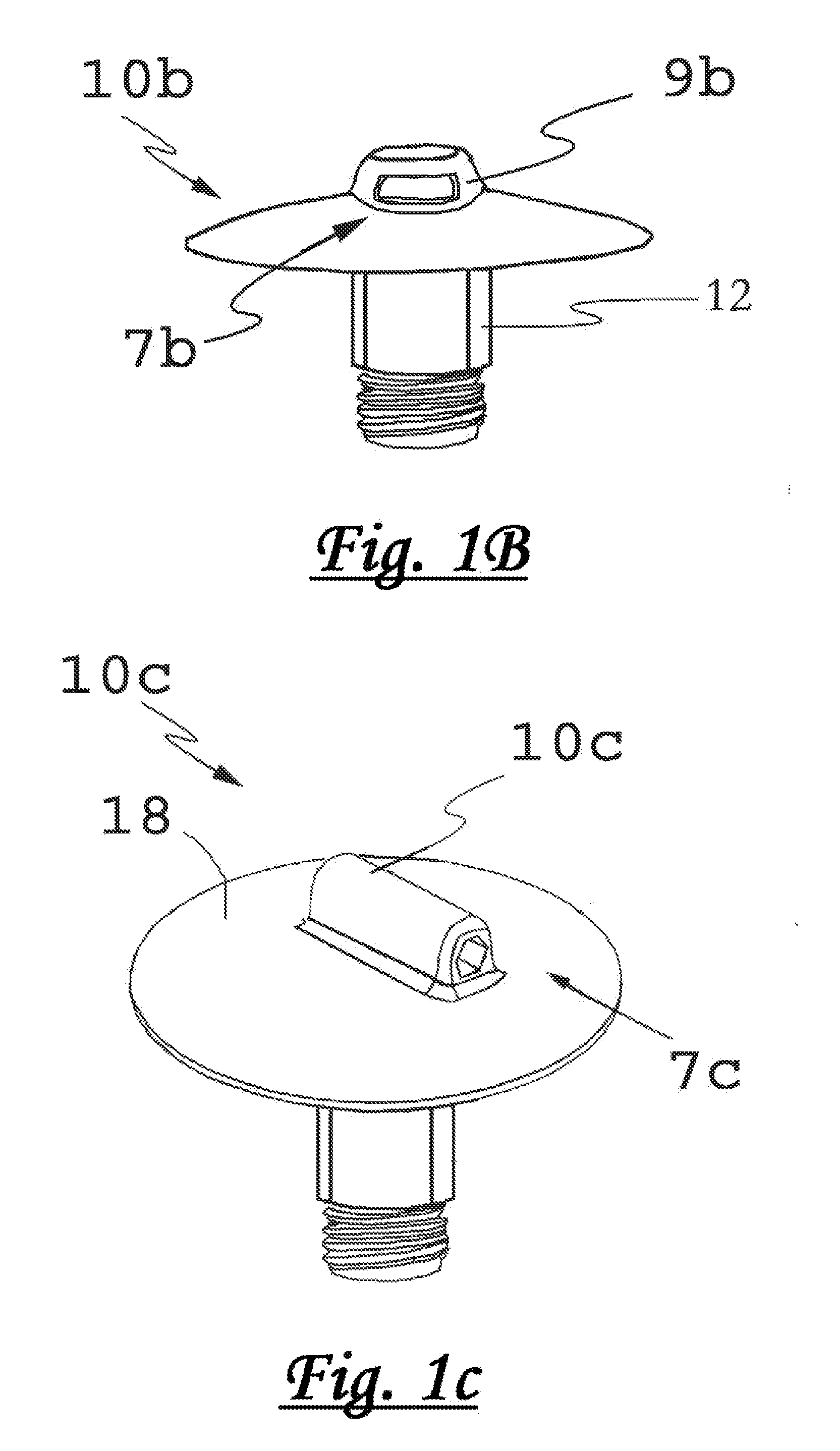
[0081]Reference now will be made in detail to the embodiments of the invention, one or more examples of which are set forth below. Each example is provided by way of explanation of the invention, not limitation of the invention. In fact, it will be apparent to those skilled in the art that various modifications and variations can be made in the present invention without departing from the scope or spirit of the invention. For instance, features illustrated or described as part of one embodiment can be used on another embodiment to yield a still further embodiment. Thus, it is intended that the present invention covers such modifications and variations as come within the scope of the appended claims and their equivalents. Other objects, features, and aspects of the present invention are disclosed in or may be determined from the following detailed description. Repeat use of reference characters is intended to represent same or analogous features, elements or steps. It is to be unders...


PUM


Abstract

Disclosed are the design and utilitarian characteristics of a support device for supporting a cover wherein such cover is typically used to cover a vehicle such as a boat or automobile. The invention includes a dome shaped support device with a depending base configured for extending through a cover. The depending base defines an interface for being associated with a support structure such as a pole and such interface may be a swivel interface. Additionally, the support device may define a suspension interface so that a tether may be used to apply a support force from above the support device. The support device may also define a swivel device configured for being associated with a support surface such as a floor.

Description

CLAIM TO PRIORITY[0001]This application is: (1) a continuation in part to application Ser. No. 29 / 416,183, filed on Mar. 20, 2012, which is a continuation in part to patent application Ser. No. 29 / 385,453, filed Feb. 14, 2011; (2) a continuation in part to U.S. Pat. No. 8,069,870 which claims priority to application 61 / 059,757, filed on Jun. 7, 2008, and application 61 / 035,345 filed on Mar. 10, 2008; (3) a continuation in part to Ser. No. 29 / 385,453, which is a continuation of Ser. No. 12 / 400,952, filed on Mar. 10, 2009 and claiming priority to application 61 / 052,415, filed on May 12, 2008; (4) a continuation in part to PCT / US09 / 36711 filed on Mar. 10, 2009; (5) a continuation in part of U.S. Pat. No. 8,069,870; and (6) a continuation in part of U.S. Pat. No. 8,220,474 of which the entire contents of all such references are incorporated herein by this reference for all that they disclose for all purposes.FIELD OF THE INVENTION[0002]Embodiments of the present invention relate in gene...

Claims


Application Information

Patent Timeline
IPC IPC(8): B60J11/00F16C11/06
CPCB60J11/00F16C11/06E04H15/16F16C11/0604F16C11/0623F16C11/069F24F7/02F16C2350/00F16C2326/30B63B17/02B60J11/04F16C2326/20Y10T403/32204Y10T403/32631Y10T403/32606E04H15/26
Inventor GRIDLEY, WILLIAM E.
Owner GRIDLEY WILLIAM E
Why Eureka
Try Eureka