Coupling for connecting two components

a technology of connecting components and couplings, applied in the direction of yielding couplings, couplings for rigid shafts, fastening means, etc., can solve the problems of insufficient precision of drive elements, wear, and thermal stress, and achieve the effect of reducing the number of components

Inactive Publication Date: 2006-08-24
WITTENSTEIN GROUP
View PDF11 Cites 0 Cited by
  • Summary
  • Abstract
  • Description
  • Claims
  • Application Information

AI Technical Summary

Benefits of technology

[0008] In the present disclosure, to compensate for a lateral offset of the clamping hub and / or centering hub it has proven to be particularly advantageous to provide a projection on the end face side which engages with a corresponding matching recess or a corresponding projection on the centering hub. In this regard, the radially and preferably circumferentially disposed clamping hub and centering hub are rigidly connected to one another by a bellows or folding bellows so that axial motion between the clamping hub and the centering hub is ensured, and a torque can be transmitted from the clamping hub to the centering hub in a rotationally fixed and play-free manner. A shaft of any given drive element, electric motor, servomotor, or the like, for example, is connected to the clamping hub. To consistently ensure a radial offset and an axial motion between the clamping hub and the centering hub, the projection provided on the end-face side of the clamping hub engages with little play in a corresponding matching recess on the end-face side of the centering hub.
[0009] To center the clamping hub with respect to the centering hub, it has been proven to be advantageous to insert in a preferably radially circumferential groove an O-ring which ensures lateral centering of both components with respect to one another.

Problems solved by technology

A disadvantage of such couplings is that they are subjected to wear, and undergo thermal stress on the drive element for which corresponding expansion of the drive shaft of the drive element must be compensated.
Drive elements frequently are not designed with sufficient precision, with the result that corresponding fluctuations of the drive element regarding play, vibration, and thermal expansion over the coupling must be compensated for, or absorbed or intercepted.
As a result, conventional couplings, preferably couplings comprising a clamping hub and centering hub which are connected to one another by a bellows, i.e., a simple or multiple folding bellows, are subjected to a certain amount of wear under excessive stress, in particular axial stress, which deactivates the coupling when the bellows ruptures.

Method used


Image

  • Coupling for connecting two components
  • Coupling for connecting two components
  • Coupling for connecting two components

Examples


Embodiment Construction

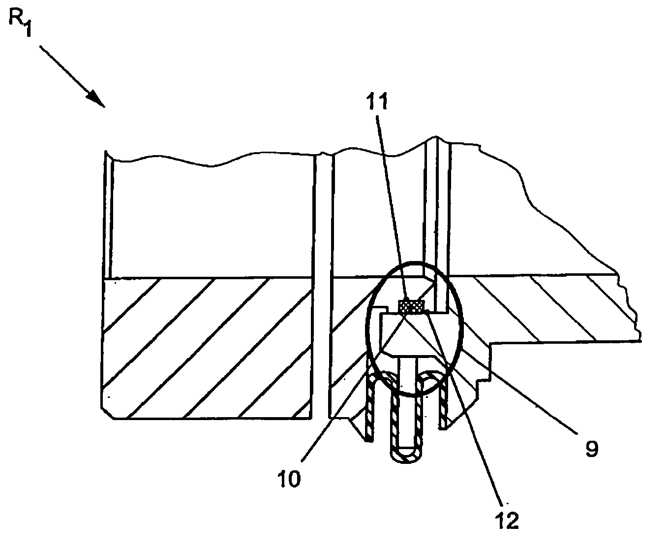
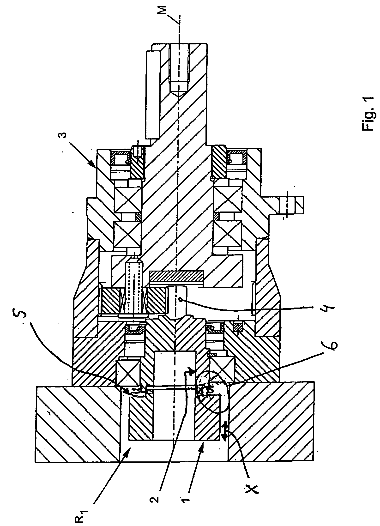
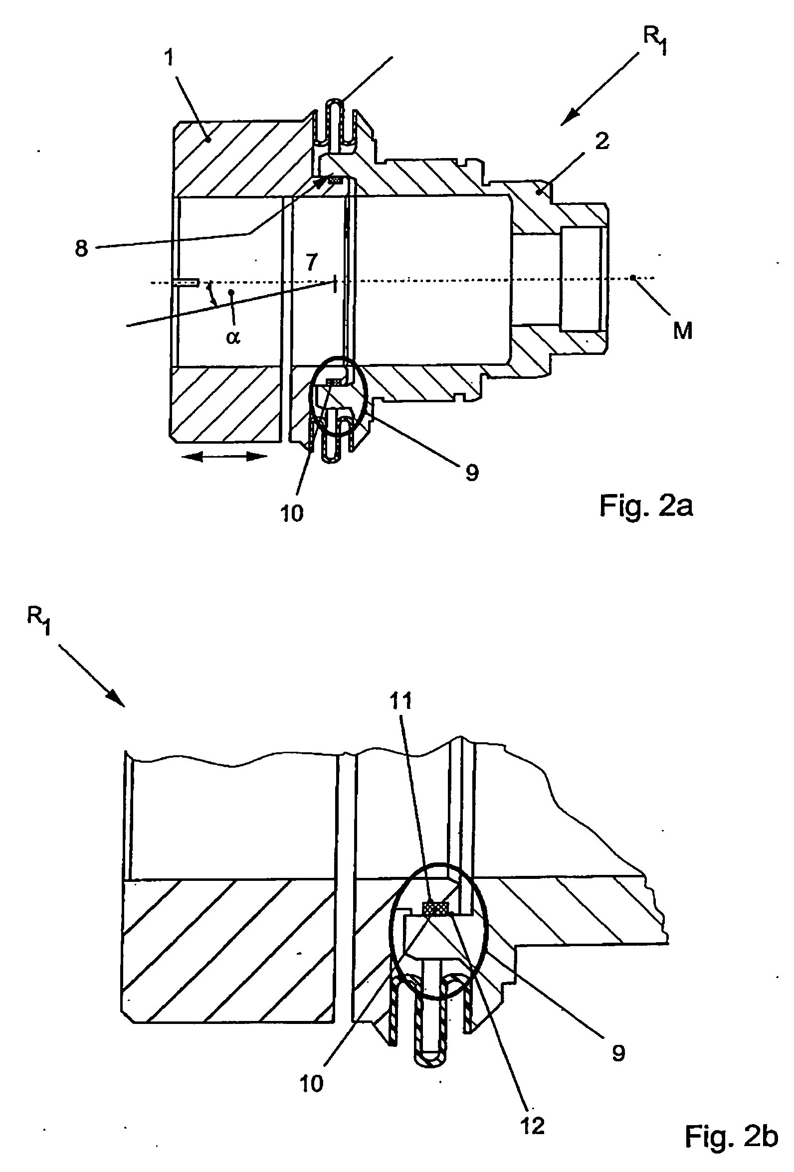
[0024] According to FIG. 1, a coupling R1 according to the disclosure comprising a clamping hub 1 as a connecting element is inserted in a drive, electric motor, servomotor, or the like (not illustrated here in greater detail) and a transmission element 3.

[0025] The centering hub 2 is used for a matched-fit insertion into the transmission element 1 and for transmission of the torque to a spur pinion 4 of the transmission 3.

[0026] To compensate for axial expansion, in particular as the result of heating of the drive element, the clamping hub 1 is mounted so as to be slightly movable with respect to the centering hub 2 in the axial direction, in the illustrated double arrow direction X, along the center axis M.

[0027] The torque of any given drive is transmitted through the centering hub 1 via a bellows 5, in particular folding bellows 6, to the centering hub 2. The bellows 5, in particular folding bellows 6, which provides radial centering between the clamping hub 1 and centering h...


PUM


Abstract

A coupling for connecting two components, such as a drive element to a drive element, transmission, or the like, having a clamping hub and a centering hub which are connected to one another in an axially displaceable manner by at least one bellows, and as additional torsional locking, the clamping hub and centering hub are connected with a positive fit and are radially locked torsionally with respect to one another.

Description

CROSS-REFERENCE TO RELATED APPLICATIONS [0001] This application claims priority to German Patent Application Serial No. 102005008920.8, filed Feb. 24, 2005, which is hereby incorporated by reference in its entirety for all purposes. BACKGROUND AND SUMMARY [0002] The present disclosure relates to a coupling for connecting two components, such as a drive element to a drive element, transmission, or the like, having a clamping hub and a centering hub which are connected to one another in an axially displaceable manner by at least one bellows. [0003] Such couplings are known and available on the market in many forms and designs. They are most commonly known as torsionally rigid compensating couplings which transmit introduced torques from one component to a second component. The coupling is usually attached to a clamping hub and a drive element such as an electric motor, servomotor, or the like, and transmits a torque to any given transmission via a centering hub. A disadvantage of such...

Claims


Application Information

Patent Timeline
Patent Type & Authority Applications(United States)
IPC IPC(8): B25G3/18
CPCY10T403/59F16D3/72F16D3/06
Inventor BAYER, THOMAS
Owner WITTENSTEIN GROUP
Why Eureka
Try Eureka