Synthesizer method utilizing variable frequency comb lines and frequency toggling

a variable frequency comb line and frequency toggling technology, applied in the field of synthesizers, can solve problems such as inability to adjust the output frequency range, and inability to achieve the desired frequency variation,

Active Publication Date: 2014-01-23
NATIONAL UNITED UNIVERSITY
View PDF12 Cites 8 Cited by
  • Summary
  • Abstract
  • Description
  • Claims
  • Application Information

AI Technical Summary

Benefits of technology

[0034]In a preferred embodiment, the DDS is varies between a first tuning word and a second tuning word for a

Problems solved by technology

However, this results in tuning holes in the output frequency range due to limitations in the FTS tuning and frequency range limitations of the PLL itself.
An additional disadvantage is the existence of close spurs due to mixer non-lineari

Method used


Image

  • Synthesizer method utilizing variable frequency comb lines and frequency toggling
  • Synthesizer method utilizing variable frequency comb lines and frequency toggling
  • Synthesizer method utilizing variable frequency comb lines and frequency toggling

Examples


example

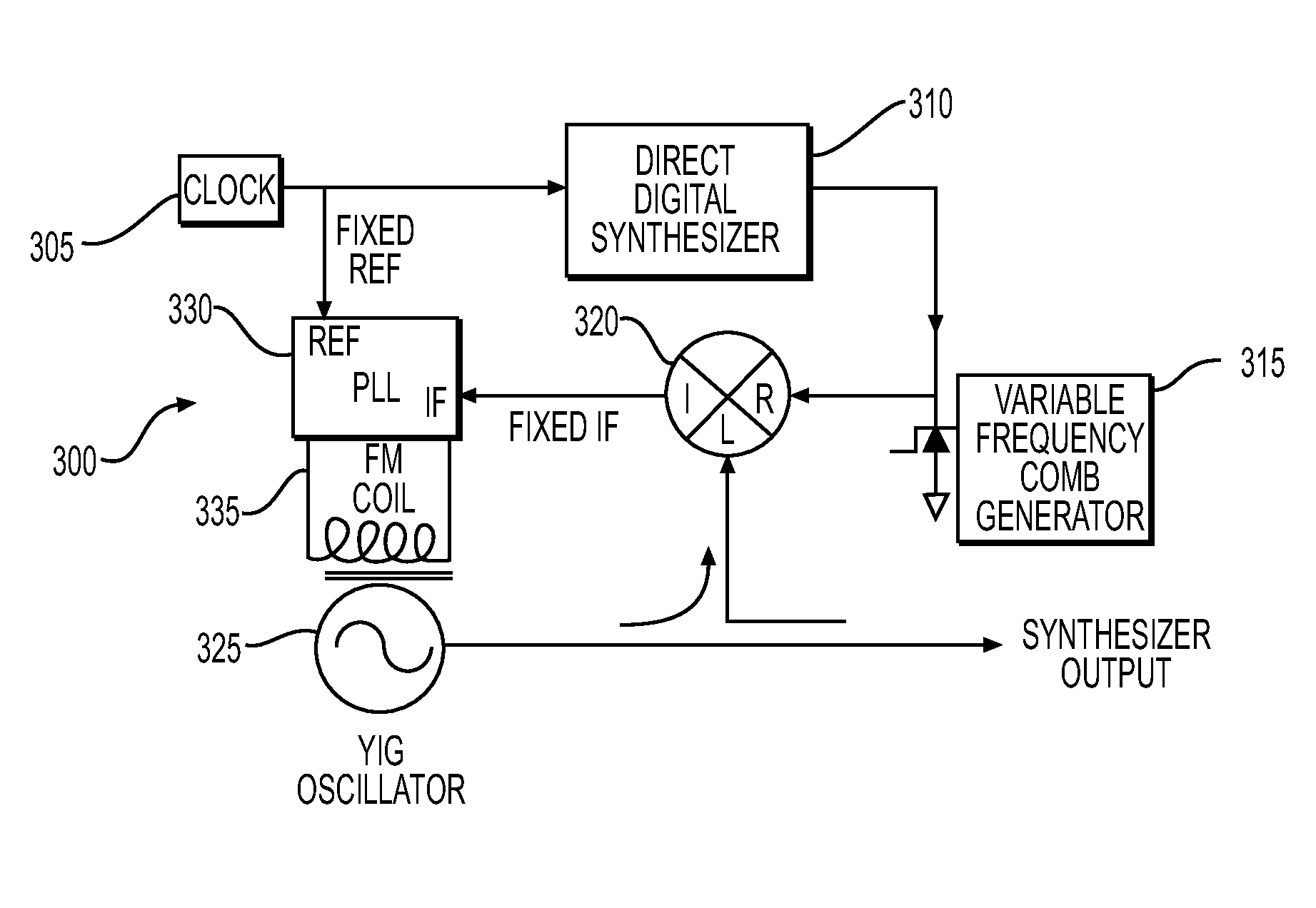
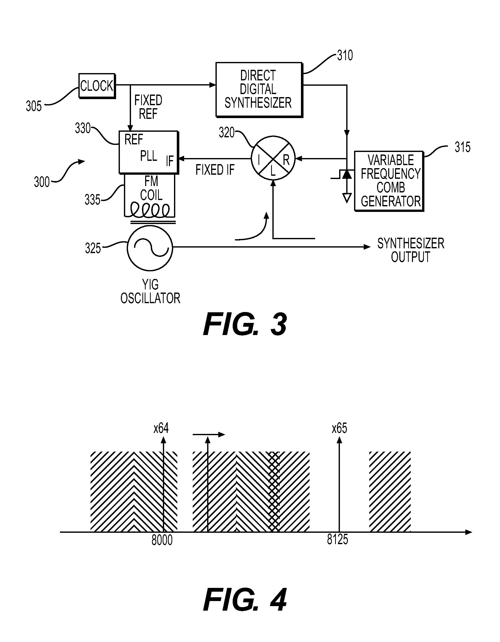
[0085]Using synthesizer 300 with the clock frequency set to 500 MHz, the nominal comb line space at ⅔ of the clock or 333.333 MHz (e.g. at the 2nd Nyquist zone), the maximum DDS tuning range set to 35 MHz, FIG. 9 shows the nominal comb lines in the 14-15 GHz range with a desired synthesizer output frequency of 14500 MHz. The comb lines lower than the desired frequency are successively move up to either ±100 MHz from the desired output frequency by adjusting upward the DDS frequency (like an accordion).

[0086]In the example, the closest comb line on the low side is times 43 and the desired output frequency can be phased locked to comb lines as low as the nominal clock frequency time 40 without violation the maximum tuning range of the DDS (see Table 1). The tuning is determined by calculating the difference between the desired comb to lock to and the desired IF (high or low) and dividing by the comb line harmonic number. 14400 MHz minus 14333.3 divided by 43 is the tuning step beyond ...


PUM


Abstract

A variable frequency synthesizer and method of outputting the variable frequency is disclosed. The synthesizer comprises a first reference frequency, a direct digital synthesizer (DDS) receiving the first reference frequency and outputting a tuned frequency, a variable frequency comb generator receiving the tuned frequency and outputting a variable frequency comb comprised of a plurality of comb lines, a mixer receiving the variable frequency comb and a signal from an oscillator and outputting an intermediate frequency, a phase lock loop (PLL) receiving a second reference frequency and the intermediate frequency and outputting a phase lock signal, and the oscillator receiving the phase lock signal and outputting a variable synthesized frequency.

Description

REFERENCE TO RELATED APPLICATIONS[0001]This application claims priority to U.S. Provisional Application No. 61 / 674,445, filed Jul. 23, 2012, entitled “Synthesizer Method Utilizing Variable Frequency Comb Lines and Frequency Dithering,” and is hereby specifically and entirely incorporated by reference.RIGHT IN THE INVENTION[0002]This invention was made with government support under Cooperative Agreement AST-0223851, between the National Science Foundation and Associated Universities, Inc., and, accordingly, the United States government has certain rights in this invention.BACKGROUND[0003]1. Field of the Invention[0004]The invention is directed to a synthesizer. Specifically, the invention is directed to a synthesizer utilizing variable frequency comb lines and toggling.[0005]2. Background of the Invention[0006]Vadim Manassewitcsh in Frequency Synthesis Theory and Design (3rd Edition, John Wiley and Sons 1987) starts Chapter 1 “A frequency synthesis is a combination of system elements...

Claims


Application Information

Patent Timeline
IPC IPC(8): H03L7/16
CPCH03L7/16H03L2207/12H03B21/025H03B2200/0054
Inventor SCOTT, RICHARD D.BRISKEN, WALTER F.LONG, ROBERT E.
Owner NATIONAL UNITED UNIVERSITY
Why Eureka
Try Eureka