
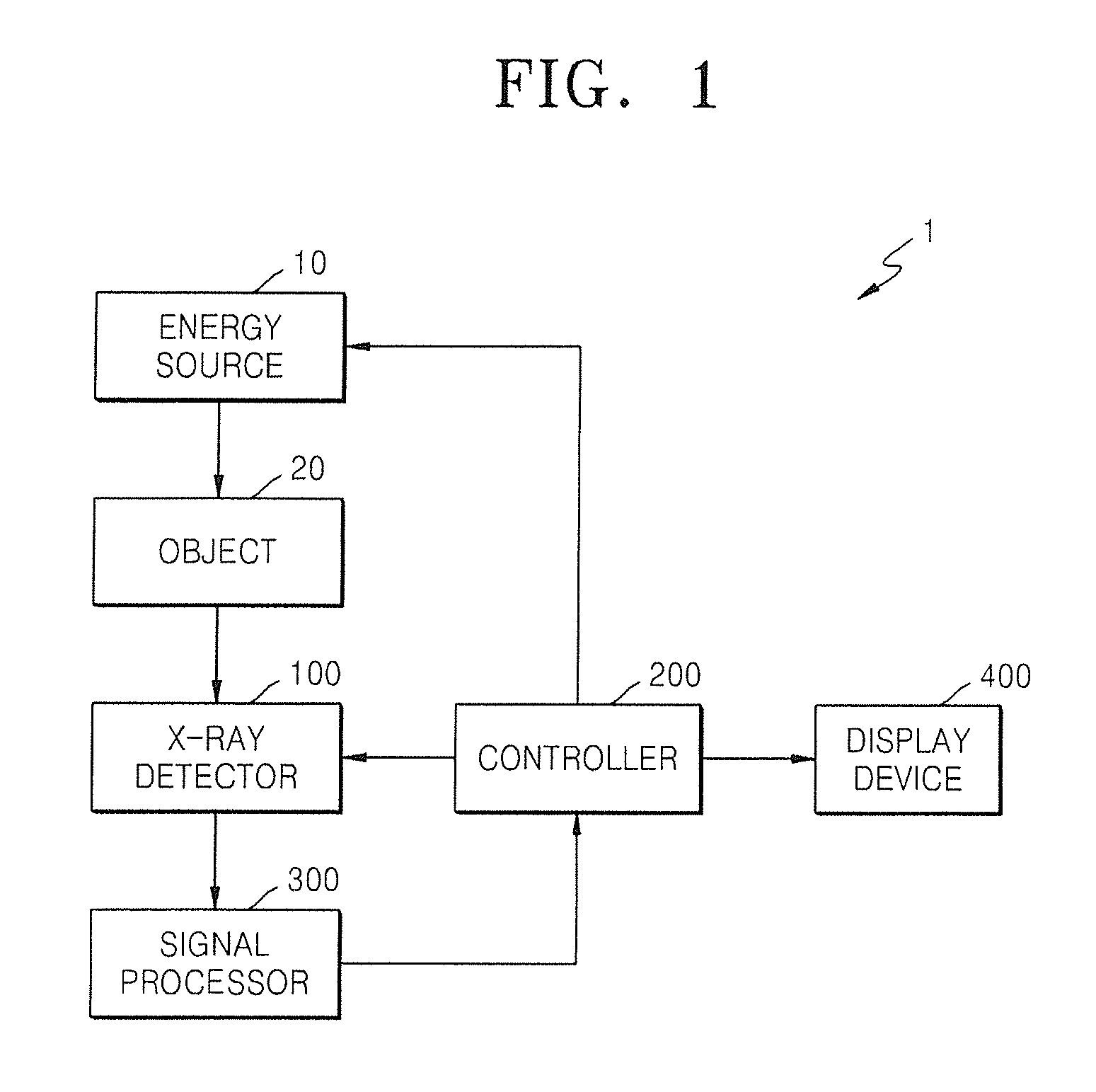
X-ray detector

a detector and x-ray technology, applied in the field of x-ray detectors, can solve the problem of deterioration of the reproducibility of a fine portion of an image, and achieve the effect of improving the modulation transfer function

Active Publication Date: 2014-01-30
SAMSUNG DISPLAY CO LTD
View PDF7 Cites 20 Cited by
  • Summary
  • Abstract
  • Description
  • Claims
  • Application Information

AI Technical Summary

Benefits of technology

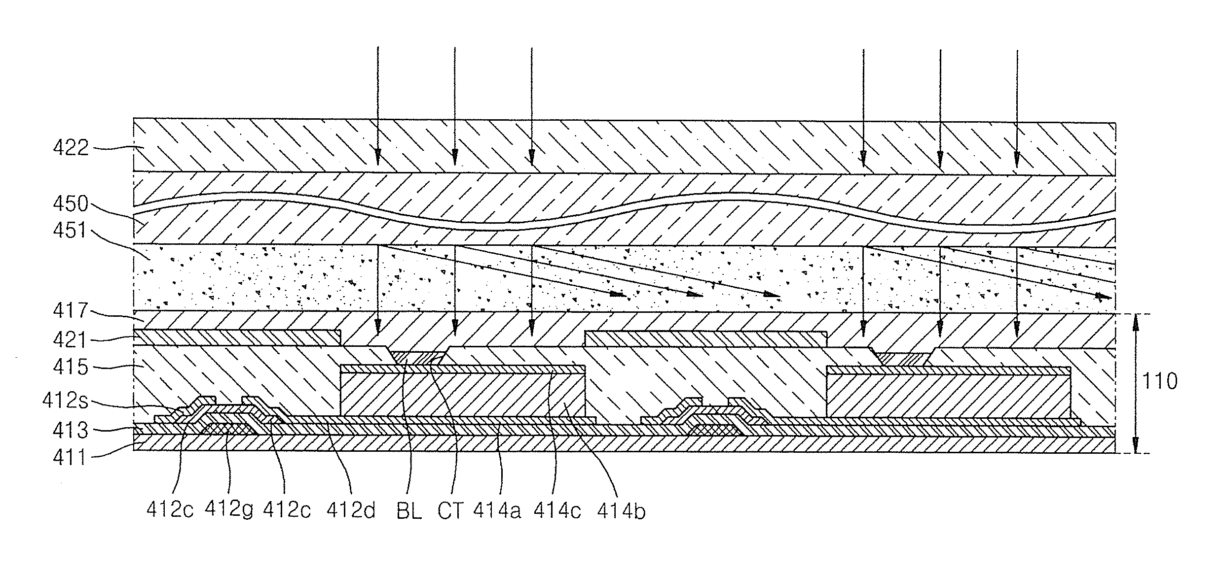
The present invention provides an X-ray detector with an improved modulation transfer function (MTF) that can detect X-rays with high accuracy. The detector includes a substrate, a photosensitive element, a circuit unit, wires, a device passivation layer, an insulating layer, a light wavelength conversion layer, and a shielding part. The shielding part can be made of various materials such as acryl-based organic material, overcoat material, or a black matrix. The scintillator layer can include materials such as CSI or GdOS. The detector can detect X-rays with high accuracy and provide better image quality.

Problems solved by technology

However, a light scattering factor exists on a path of light incident on a photosensitive diode, and thus, the reproducibility of a fine portion of an image tends to deteriorate.

Method used


Image

  • X-ray detector
  • X-ray detector
  • X-ray detector

Examples


Embodiment Construction

[0036]Reference will now be made in detail to example embodiments, examples of which are illustrated in the accompanying drawings. However, the present invention may be embodied in many different forms and should not be construed as being limited to embodiments set forth herein. Rather, these embodiments are provided so that this disclosure will be thorough and complete, and will fully convey the scope of the invention to those skilled in the art. Like reference numerals denote like elements throughout the drawings.

[0037]As used herein, the term “and / or” includes any and all combinations of one or more of the associated listed items. It will be understood that, although the terms ‘first’, ‘second’, etc. may be used herein to describe various elements, components, and / or sections, these elements, components, and / or sections should not be limited by these terms. These terms are only used to distinguish one element, component, or section from another element, component, or section. Thu...


PUM


Abstract

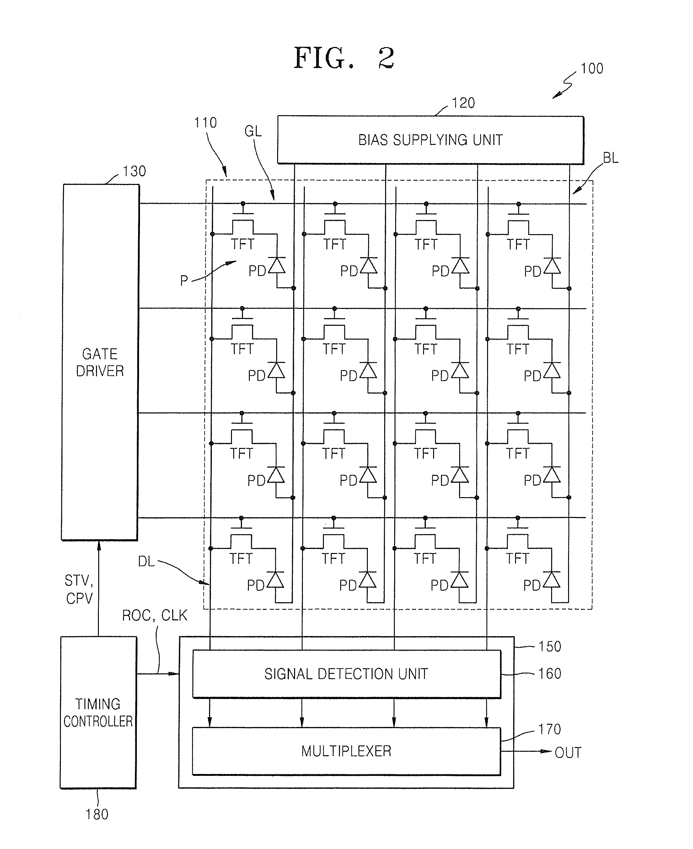
An X-ray detector including: a substrate that is divided into a light detection area and a non-detection area and includes a plurality of pixels; a photodiode disposed on the light detection area; a thin film transistor that is disposed on the non-detection area and is electrically connected to a lower portion of the photodiode; a plurality of wires that are electrically connected to the thin film transistor and are positioned on the non-detection area; at least one insulating layer disposed so as to cover at least the thin film transistor and the plurality of wires; a scintillator layer disposed on the at least one insulating layer over an entire surface of the substrate; and a shielding part disposed between the at least one insulating layer and the scintillator layer to shield the non-detection area.

Description

CROSS-REFERENCE TO RELATED PATENT APPLICATION[0001]This application claims priority to and the benefit of Korean Patent Application No. 10-2012-0082783, filed on Jul. 27, 2012, in the Korean Intellectual Property Office, the disclosure of which is incorporated herein in its entirety by reference.BACKGROUND[0002]1. Field[0003]Aspects of the present invention relate to an X-ray detector.[0004]2. Description of the Related Art[0005]X-rays are transmitted easily through objects due to their short wavelengths. The amount of X-rays transmitted through an object is dependent on the internal density of the object through which the X-rays are traveling. As a result, the interior of an object may be indirectly imaged based on an amount of X-rays transmitted through the object.[0006]An X-ray detector is a device for detecting an amount of X-rays transmitted through an object. The X-ray detector may detect the amount of X-rays transmitted through the object and display an interior of the object...

Claims


Application Information

Patent Timeline
Patent Type & Authority Applications(United States)
IPC IPC(8): H01L31/118
CPCH01L31/118H01L27/14603H01L27/14623H01L27/14632H01L27/14663G01T1/20183H01L31/115
Inventor KIM, DONG-HYUK
Owner SAMSUNG DISPLAY CO LTD
Learn More