Zoom lens and image pickup apparatus including the same
a technology of zoom lens and image pickup, which is applied in the direction of optics, instruments, optical elements, etc., can solve the problems of difficult to obtain high optical performance over the entire zoom range, and achieve the effect of high optical performance and high zoom ratio
- Summary
- Abstract
- Description
- Claims
- Application Information
AI Technical Summary
Benefits of technology
Problems solved by technology
Method used
Image

Examples
embodiment 1
[0134]In the following, a lens structure according to Embodiment 1 of the present invention is described.
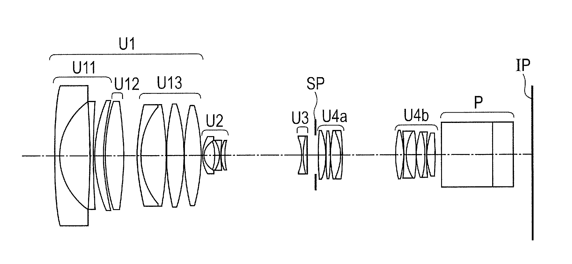
[0135]FIG. 1 is a lens cross-sectional view when an object at infinity is focused at a wide angle end of a zoom lens according to Embodiment 1(Numerical Embodiment 1) of the present invention.
[0136]A first lens unit U1 has positive refractive power that is fixed during the magnification-varying. The first lens unit U1 includes, in order from the object side, the front first lens unit U11 having negative refractive power as a fixed lens unit, the middle first lens unit U12 having positive refractive power as a focus lens unit, and the rear first lens unit U13 having positive refractive power as a fixed lens unit. A second lens unit U2 (variator lens unit) has negative refractive power for varying magnification and moves to the image side during magnification-varying from the wide angle end (short focal length end) to a telephoto end (long focal length end). A third lens unit U3 (c...
embodiment 2
[0147]In the following, a lens structure according to Embodiment 2 of the present invention is described.
[0148]FIG. 3 is a lens cross-sectional view when an object at infinity is focused at a wide angle end of a zoom lens according to Embodiment 2 (Numerical Embodiment 2) of the present invention.
[0149]A first lens unit U1 has positive refractive power that is fixed during the magnification-varying. The first lens unit U1 includes, in order from the object side, the front first lens unit U11 having negative refractive power as a fixed lens unit, the middle first lens unit U12 having positive refractive power as a focus lens unit, and the rear first lens unit U13 having positive refractive power as a fixed lens unit. A second lens unit U2 (variator lens unit) has negative refractive power for varying magnification and moves to the image side during magnification-varying from the wide angle end (short focal length end) to the telephoto end (long focal length end). A third lens unit U3...
embodiment 3
[0160]In the following, a lens structure according to Embodiment 3 of the present invention is described.
[0161]FIG. 5 is a lens cross-sectional view when an object at infinity is focused at a wide angle end of a zoom lens according to Embodiment 3 (Numerical Embodiment 3) of the present invention.
[0162]A first lens unit U1 has positive refractive power that is fixed during the magnification-varying. The first lens unit U1 includes, in order from the object side, the front first lens unit U11 having negative refractive power as a fixed lens unit, the middle first lens unit U12 having positive refractive power as a focus lens unit, and the rear first lens unit U13 having positive refractive power as a fixed lens unit. A second lens unit U2 (variator lens unit) has negative refractive power for varying magnification and moves to the image side during magnification-varying from the wide angle end (short focal length end) to the telephoto end (long focal length end). A third lens unit U3...
PUM
 Abstract
Description
Claims
Application Information
 - R&D
- Intellectual Property
- Life Sciences
- Materials
- Tech Scout
- Unparalleled Data Quality
- Higher Quality Content
- 60% Fewer Hallucinations
Browse by: Latest US Patents, China's latest patents, Technical Efficacy Thesaurus, Application Domain, Technology Topic, Popular Technical Reports.
© 2025 PatSnap. All rights reserved.Legal|Privacy policy|Modern Slavery Act Transparency Statement|Sitemap|About US| Contact US: help@patsnap.com