Ankle Nail Assembly

a technology of an ankle joint and a screw is applied in the field of surgical methods and medical devices to fuse bones, which can solve the problems of affecting the healing effect of the bone, the deformation of the joint, and the more particularly of the ankle joint, and the size of the wound

Inactive Publication Date: 2014-01-30
OSTEOMED
View PDF0 Cites 6 Cited by
  • Summary
  • Abstract
  • Description
  • Claims
  • Application Information

AI Technical Summary

Problems solved by technology

In certain circumstances, a joint, and more particularly an ankle joint, is so degraded that it becomes necessary to prevent the joint from moving because other, less-severe surgical operations, such as those that include implanting an ankle prosthesis, would be ineffective.
While the placement of the plate during surgery is easier, the size of the wound presents an issue because installation of the plate requires larger operating areas on the foot.
The third method includes a fusion nail that is inserted through a smaller opening on the bottom of the foot into the intramedullary canal of the tibia, which impacts the movement of the subtalar joint and can result in the patient having a club foot gate.

Method used


Image

  • Ankle Nail Assembly
  • Ankle Nail Assembly
  • Ankle Nail Assembly

Examples


Embodiment Construction

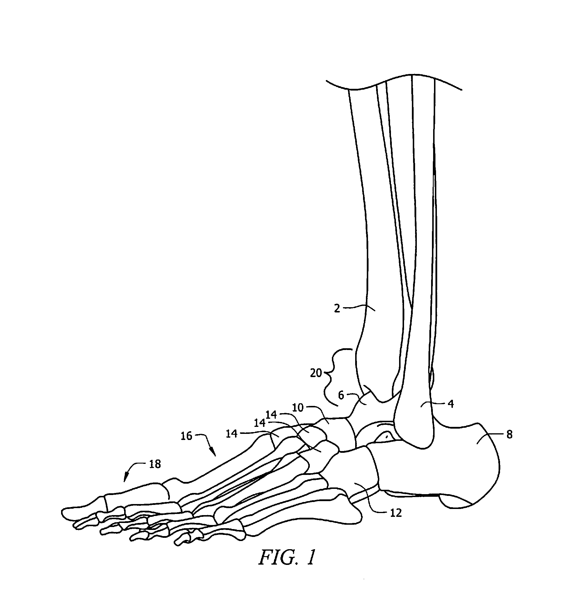
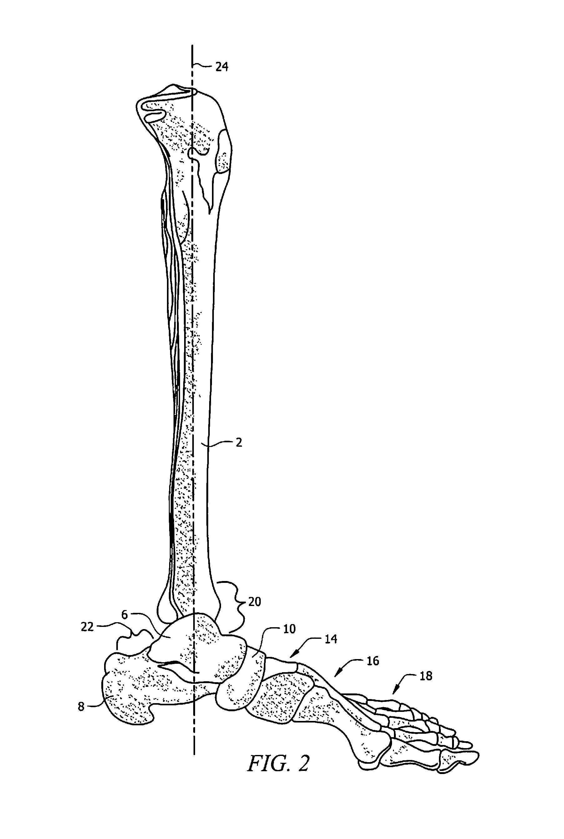
[0021]FIG. 1 illustrates a lateral view (outside view) of the skeleton of a left foot, ankle and distal leg portion. FIG. 2 illustrates a medial lateral view (inside view) of a left foot, ankle and lower leg skeleton. FIG. 3 illustrates a back, or posterior, view of the skeleton of a left foot, ankle and distal leg portion. Referring to FIGS. 1 and 2, the distal leg portion includes tibia 2 and fibula 4. The bones of the ankle and foot include: talus 6, calcaneus 8, navicular 10, cuboid 12, cuneiforms 14, metatarsals 16, and phalanges 18. In particular, ankle joint 20 comprises tibia 2, fibula 4, and talus 6. Referring to FIGS. 1 and 2, tibia 2 forms the inside, or medial, portion of ankle joint 20, fibula 4 forms the lateral, or outside portion of ankle joint 20 and talus 6 is the bone located underneath tibia 2 and fibula 4. In the preferred embodiment, the proffered procedures typically immobilize joint 20 by fusing tibia 2 and talus 6.

[0022]Referring to FIGS. 1 and 2, subtalar j...


PUM


Abstract

The present disclosure provides methods and devices that allow for rotational control, compression and fusion of the ankle as required for treatment while providing additional mobility in the movement of the foot. The devices of the present disclosure are configured to go through the talus and tibia for fusion of ankle joint while avoiding the calcaneus and subtalar joint. According to a first aspect, exemplary embodiments of the present disclosure are curved to provide sufficient area for rotational control and compression of the ankle bones. According to a second aspect, exemplary embodiments of the nails of the present disclosure are configured to be placed at an angle with respect to the intramedullary canal.

Description

CROSS-REFERENCE TO RELATED APPLICATIONS[0001]The present application claims priority to co-pending U.S. Provisional Patent Application No. 61 / 673,949, entitled “ANKLE NAIL ASSEMBLY,” filed Jul. 20, 2012, the disclosure of which is hereby incorporated herein by reference in its entirety.TECHNICAL FIELD[0002]The present disclosure relates generally to methods and medical devices to fuse bones that form a joint, and more particularly relates to methods and medical devices for fusing bones in an ankle joint.BACKGROUND[0003]In certain circumstances, a joint, and more particularly an ankle joint, is so degraded that it becomes necessary to prevent the joint from moving because other, less-severe surgical operations, such as those that include implanting an ankle prosthesis, would be ineffective. The procedure to fuse bones to immobilize the joint is called arthrodesis.[0004]The procedure effectively eliminates almost all mobility of a joint. While there are many methods currently availabl...

Claims


Application Information

Patent Timeline
Patent Type & Authority Applications(United States)
IPC IPC(8): A61B17/84
CPCA61B17/846A61B17/8872
Inventor BALES, JOEL
Owner OSTEOMED
Why Eureka
Try Eureka