
Engine cooling fan

a technology for cooling fans and engines, applied in the direction of engine cooling apparatus, liquid fuel engines, mechanical apparatus, etc., can solve the problem of increased blade deflection

Inactive Publication Date: 2014-02-13
MULTI WING INT
View PDF8 Cites 3 Cited by
  • Summary
  • Abstract
  • Description
  • Claims
  • Application Information

AI Technical Summary

Benefits of technology

The design of the blade is important to prevent it from deflecting under certain forces. By creating a blade that the forces act on, the resulting force vector is in the direction of the center line, which prevents any forces from acting on the blade in a way that would cause it to deflect. This design also allows for large tensile forces to cause minimal elongation of the blade. By preventing the blade from deflecting, the design ensures the blade stays strong and stable during use.

Problems solved by technology

In relation to engine cooling fans is it a known problem that with an increasing rotational speed, an increased deflection of the blades is experienced.
This causes the problem that the structure into which the cooling fan is build must provide enough clearance to allow the blades to deflect such that the fan is not prevented from rotating due to the deflecting blades blocking the rotation.

Method used


Image

  • Engine cooling fan
  • Engine cooling fan
  • Engine cooling fan

Examples


Embodiment Construction

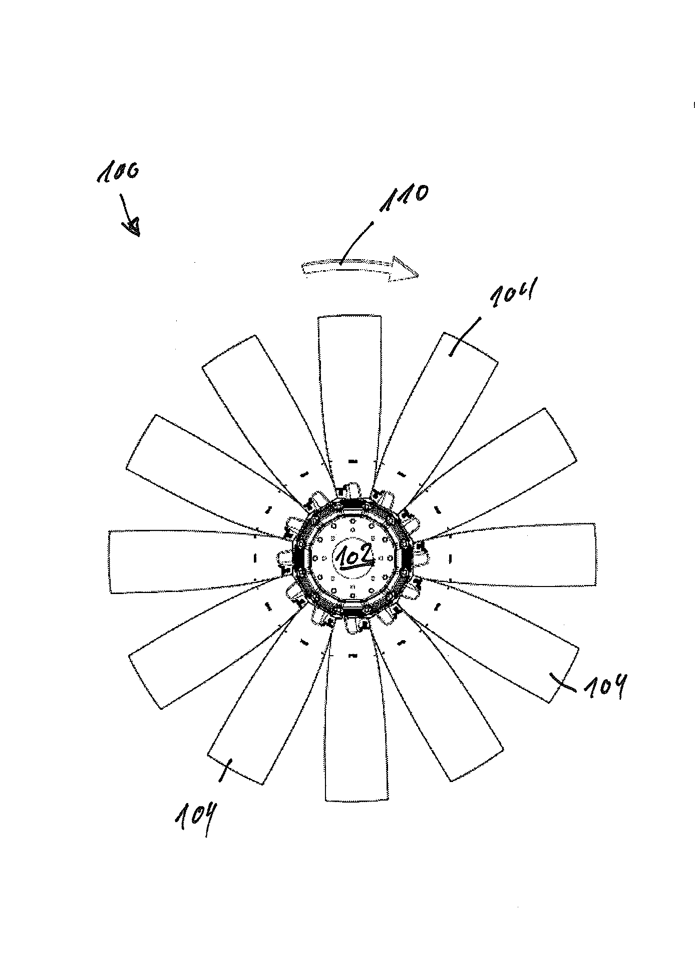
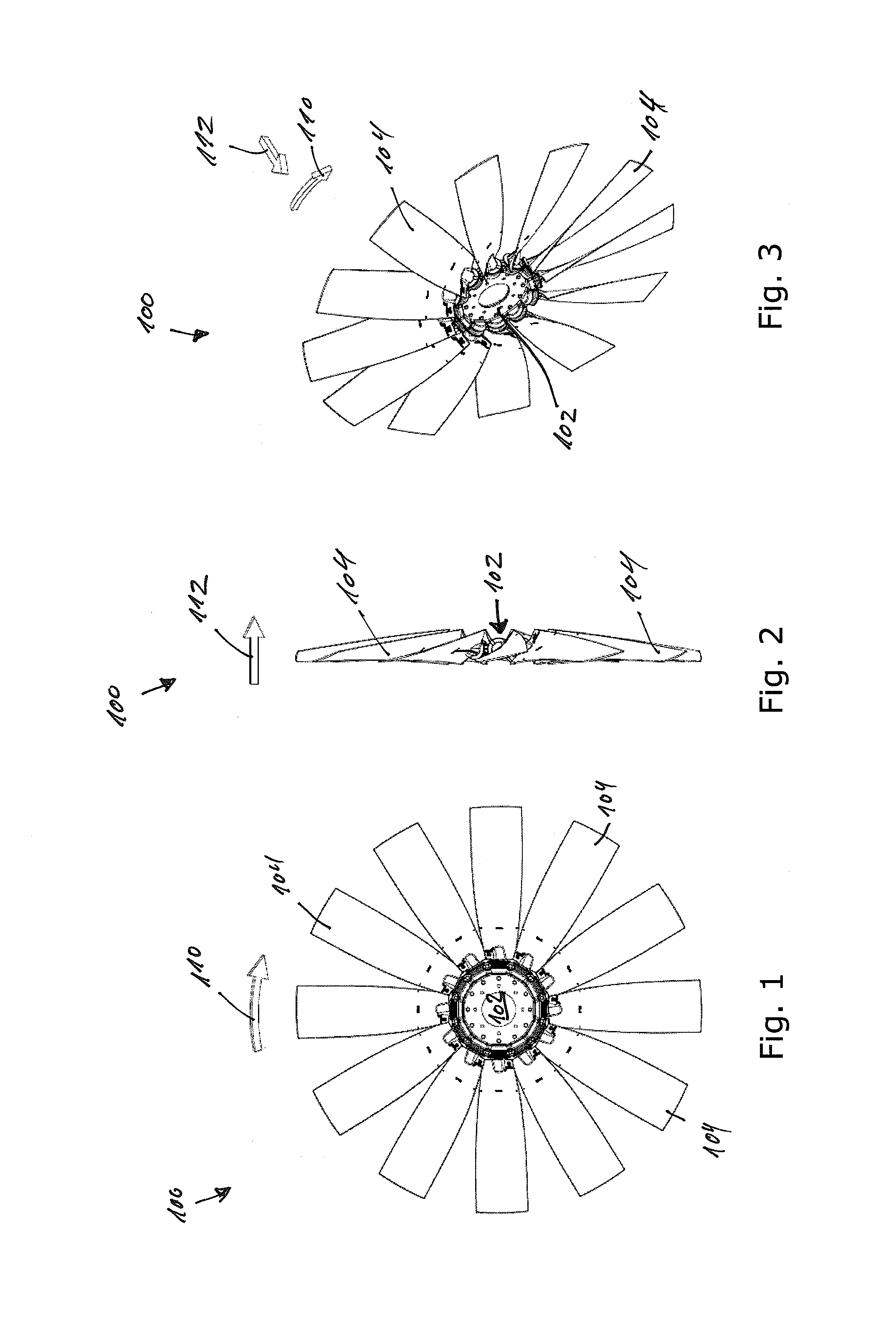
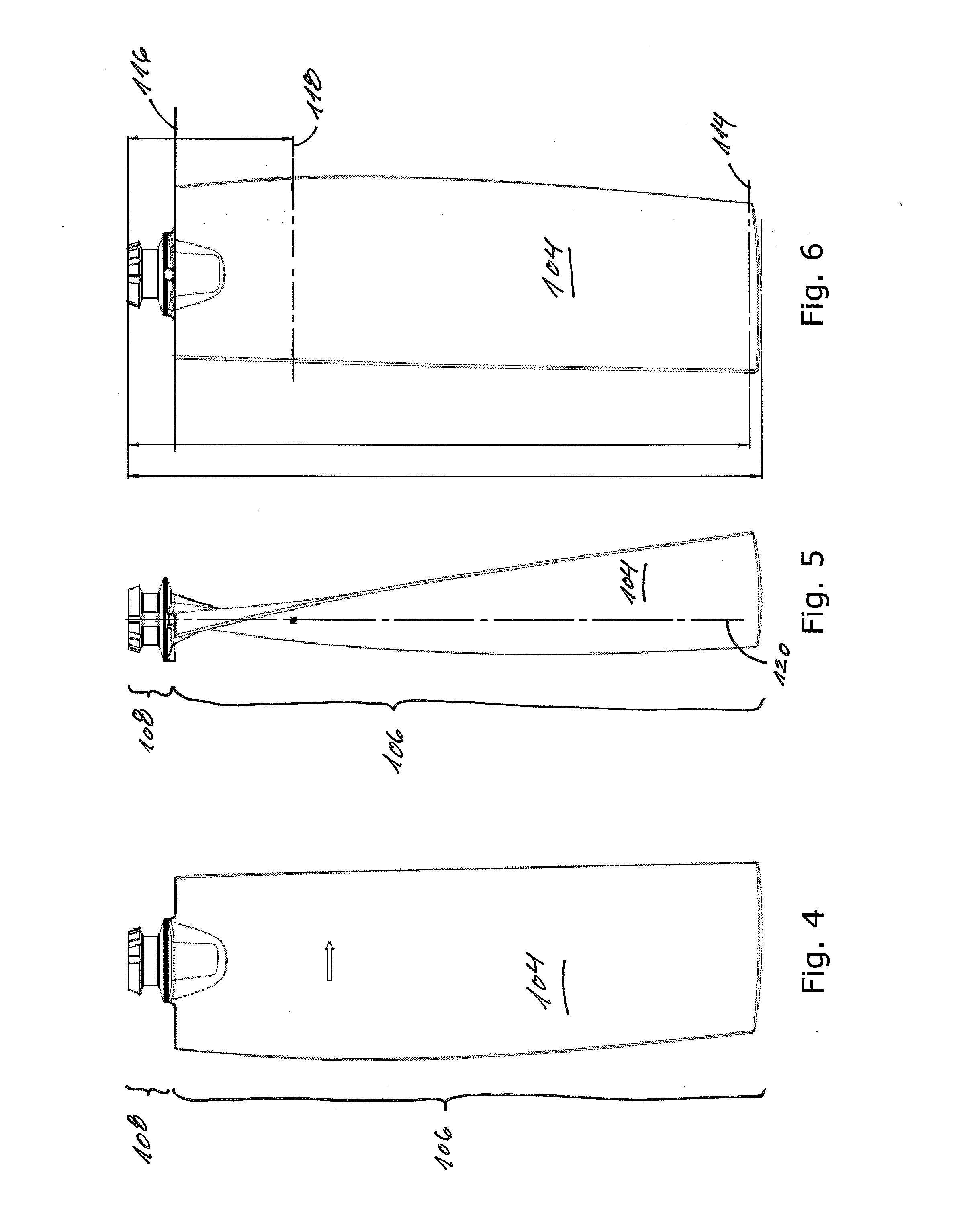
[0004]In a FIRST aspect the present invention relates to an engine cooling fan comprising a hub and a plurality of blades each of which extends away from the hub, wherein the hub defines a rotation axis about which the hub is adapted to rotate during operation; wherein each blade defines an attachment part, an air moving part, and a center line extending in a longitudinal direction of the blade between a tip end and a hub end of the blade; and wherein at least a first part of the center line extends in a direction transverse to a normal of the rotation axis of the hub.

[0005]In the context of the present invention, the term ‘engine cooling fan’ shall be understood as any fan which is suitable for cooling an engine, either by cooling a radiator which is used to cool a cooling medium that is circulated between the radiator and the engine and / or by cooling the engine directly.

[0006]The hub will typically be adapted to be connected or fastened to an axle which is rotated so as to cause t...


PUM


Abstract

An engine cooling fan (100) comprising a hub (102) and a plurality of blades (104) each of which extends away from the hub (102), wherein the hub (102) defines a rotation axis about which the hub (102) is adapted to rotate during operation; wherein each blade (104) defines an attachment part (108), an air moving part (106), and a center line extending in a longitudinal direction of the blade (104) between a tip end and a hub end of the blade; wherein at least a first zone of the center line extends in a direction transverse to a normal of the rotation axis of the hub (102). Moreover the present invention relates to a blade (104) for use in the fan (100) and a kit comprising the blade (104) and the fan (100).

Description

FIELD OF THE INVENTION[0001]The present invention relates to an engine cooling fan with a hub and a plurality of blades. In particular the present invention relates to an engine cooling fan wherein a center line of at least a part of the blade extends in direction transverse to a normal of an axis of rotation of the hub. Furthermore, the present invention relates to a blade for an engine cooling fan. Moreover, the present invention relates to a kit comprising a hub and a plurality of blades.BACKGROUND OF THE INVENTION[0002]In relation to engine cooling fans is it a known problem that with an increasing rotational speed, an increased deflection of the blades is experienced. This causes the problem that the structure into which the cooling fan is build must provide enough clearance to allow the blades to deflect such that the fan is not prevented from rotating due to the deflecting blades blocking the rotation.[0003]It is an object of the present invention to provide an engine cooling...

Claims


Application Information

Patent Timeline
Patent Type & Authority Applications(United States)
IPC IPC(8): F01P1/00
CPCF01P1/00F04D29/384F04D29/023F04D29/36F05D2300/43F05D2300/10
Inventor CHRISTENSEN-DALSGAARD, CLAUS
Owner MULTI WING INT
Learn More