
Card connector having a housing with fastening blocks for mounting a circuit board

Inactive Publication Date: 2014-02-13
PROCONN TECH CO LTD
View PDF0 Cites 8 Cited by
  • Summary
  • Abstract
  • Description
  • Claims
  • Application Information

AI Technical Summary

Benefits of technology

The card connector described in this patent is designed to be securely attached to a circuit board. The connector uses fastening blocks that are securely attached to the sides of the insulating housing, making sure that it is firmly fixed and cannot become loose or tiltable during use. This improves the stability and reliability of the card connector.

Problems solved by technology

As a result, the card connector easily looses relative to the circuit board.

Method used


Image

  • Card connector having a housing with fastening blocks for mounting a circuit board
  • Card connector having a housing with fastening blocks for mounting a circuit board
  • Card connector having a housing with fastening blocks for mounting a circuit board

Examples


Embodiment Construction

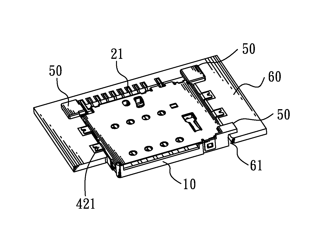
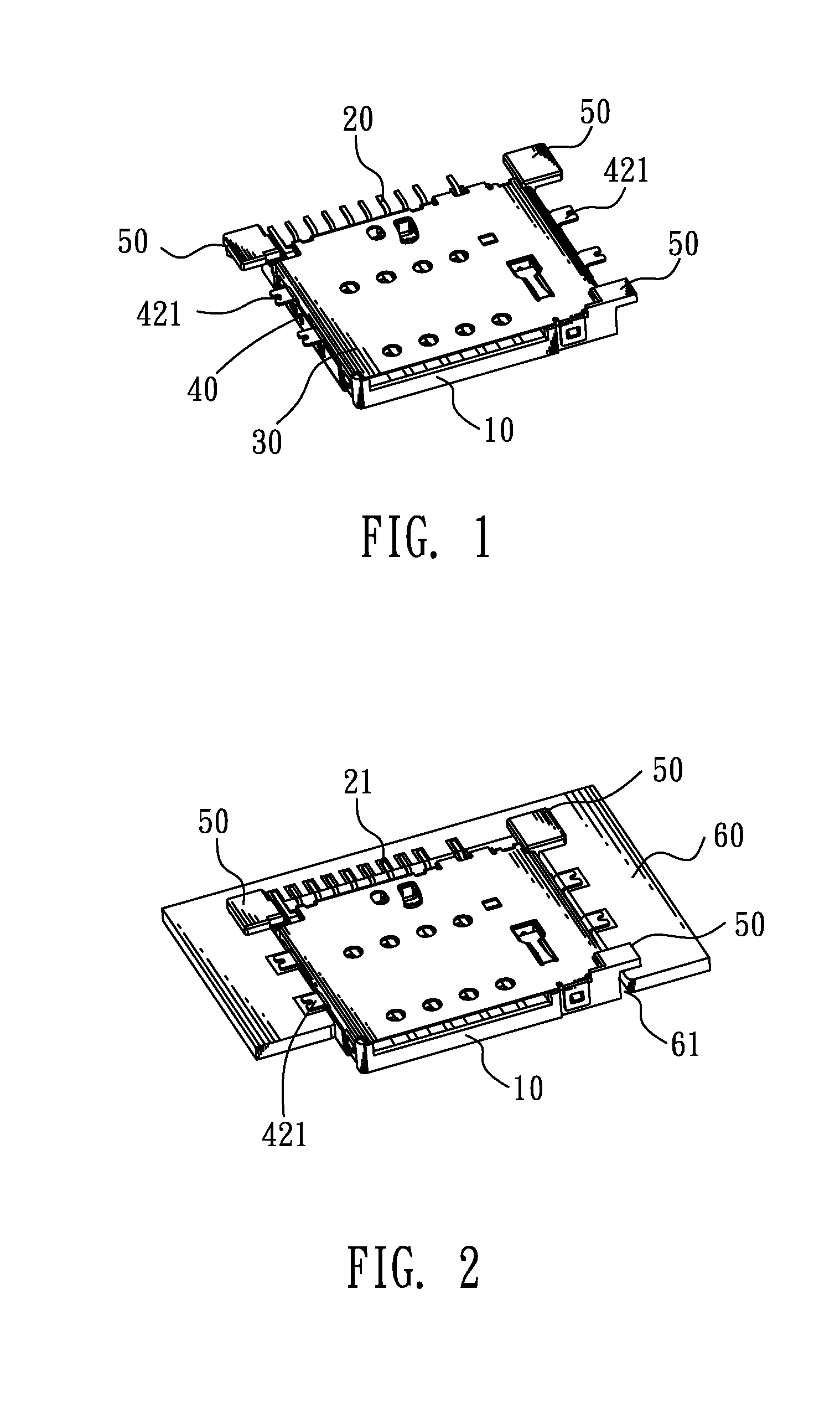
[0011]With reference to FIG. 1 and FIG. 2, a card connector according to an embodiment of the present invention is adapted for being mounted to a circuit board 60. The card connector includes an insulating housing 10, a plurality of electrical terminals 20, a shielding shell and a plurality of fastening blocks 50.

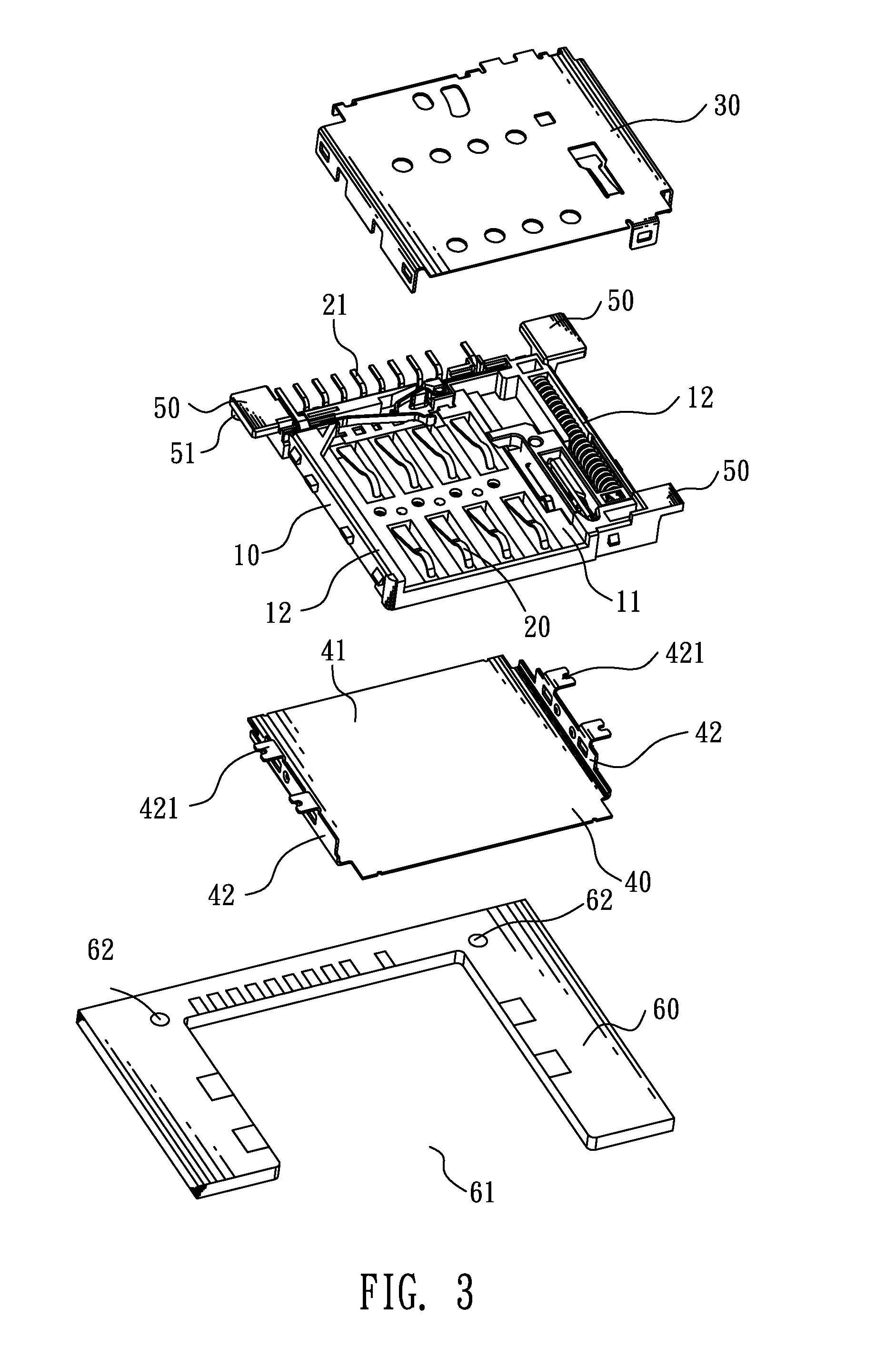
[0012]Referring to FIG. 2 and FIG. 3, the insulating housing 10 defines a receiving room 11 passing through a top and a front thereof. A pair of side walls 12 is formed at two opposite sides of the receiving room 11. The electrical terminals 20 are disposed in the insulating housing 10 and electrically project upward into the receiving room 11. The shielding shell encloses the insulating housing 10. The fastening blocks 50 are apart secured to outsides of the side walls 12 of the insulating housing 10. The circuit board 60 defines a mounting cavity 61. The card connector is mounted in the mounting cavity 61 of the circuit board 60, and the fastening blocks 50 are fixed on t...


PUM


Abstract

A card connector is adapted for being mounted to a circuit board defining a mounting cavity. The card connector includes an insulating housing defining a receiving room passing through a top and a front thereof, a plurality of electrical terminals disposed in the insulating housing and electrically projecting upward into the receiving room, a shielding shell enclosing the insulating housing, and a plurality of fastening blocks. A pair of side walls is formed at two opposite sides of the receiving room. The fastening blocks are apart secured to outsides of the side walls. The card connector is mounted in the mounting cavity of the circuit board, and the fastening blocks are fixed on the circuit board around the mounting cavity. Because the fastening blocks are not easily deformed, the card connector can be firmly fixed in the circuit board and avoids being slanted downward in use.

Description

BACKGROUND OF THE INVENTION[0001]1. Field of the Invention[0002]The present invention relates to a card connector, and more particularly to a card connector adapted for being embedded in a circuit board.[0003]2. The Related Art[0004]With the development of electronic technology, the trend in connector design is towards miniaturization and thin profile, and a card connector adapted for being embedded in a circuit board comes with the tide of fashion. The card connector generally includes an insulating housing, a plurality of electrical terminals disposed in the insulating housing, and a shielding shell enclosing the insulating housing. Each of the electrical terminals has a soldering tail projecting behind the insulating housing. The shielding shell has two side plates die-cut and then oppositely bent outward to form a plurality of soldering feet. The circuit board defines a mounting cavity for mounting the card connector therein. The soldering tails of the electrical terminals and t...

Claims


Application Information

Patent Timeline
IPC IPC(8): H01R12/73H01R13/6594
CPCH01R13/6594
Inventor HSU, YA-HUIYU, TA-CHIH
Owner PROCONN TECH CO LTD
Features
  • Generate Ideas
  • Intellectual Property
  • Life Sciences
  • Materials
  • Tech Scout
  • Unparalleled Data Quality
  • Higher Quality Content
  • 60% Fewer Hallucinations
Learn More