Surgical forceps

Inactive Publication Date: 2014-02-13
FRIMAND RONNOW CARL FREDRIK
View PDF2 Cites 6 Cited by
  • Summary
  • Abstract
  • Description
  • Claims
  • Application Information

AI Technical Summary

Benefits of technology

[0015]The area between the finger grips may be free from leg portions, which is a way of assuring a more versatile use since it is easier for the user to find the most comfortable and

Problems solved by technology

Firstly, the needle might not release easily from the needle holder, hence causing tissue damage when the needle holder is being removed.
Secondly, and more importantly, holding the needle holder at the intended location, i.e. at the finger grips of the needle holder, does not allow for a more refined suturing action with higher demands on precision.
Except for being time-con

Method used


Image

  • Surgical forceps
  • Surgical forceps
  • Surgical forceps

Examples


Embodiment Construction

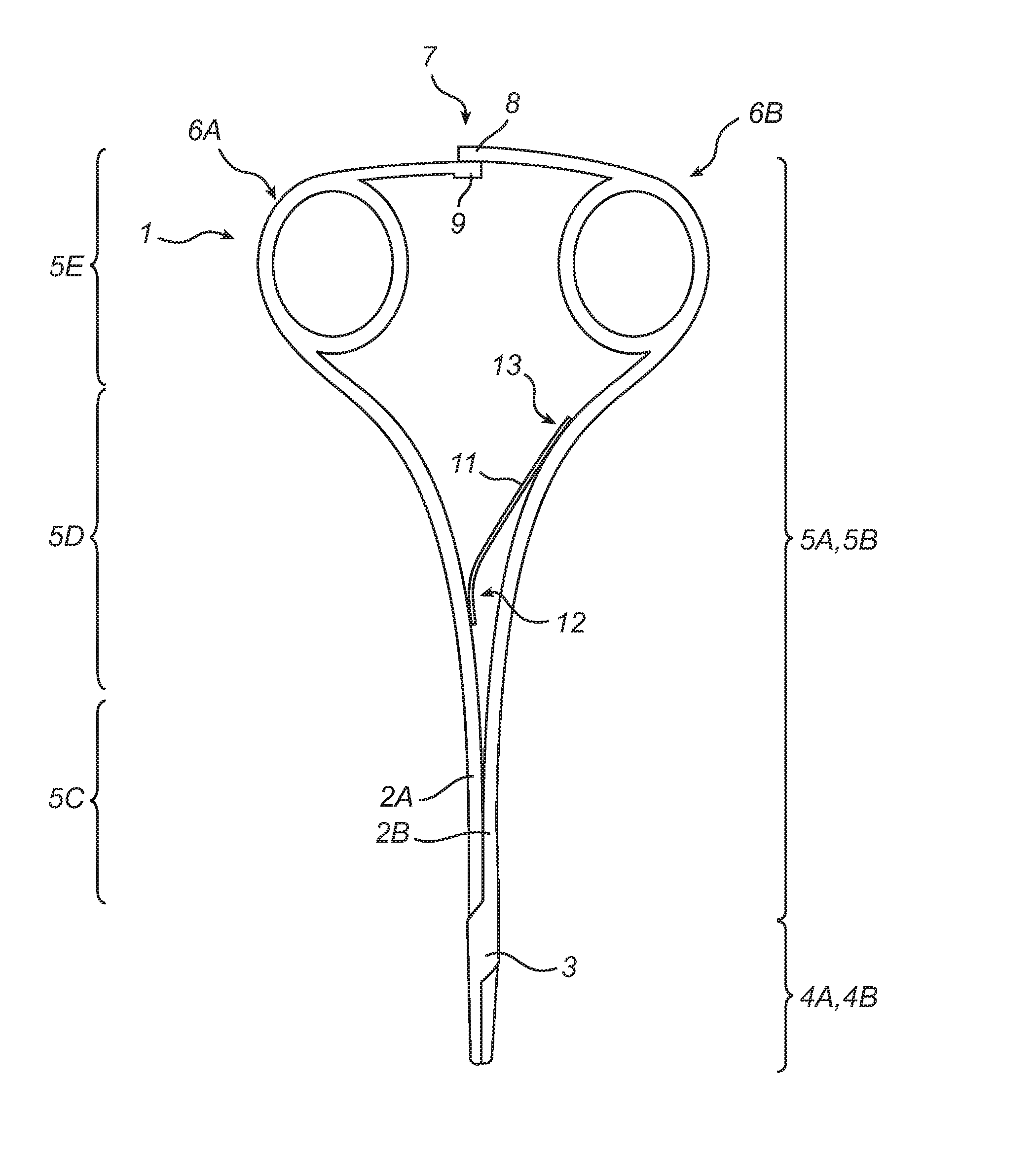
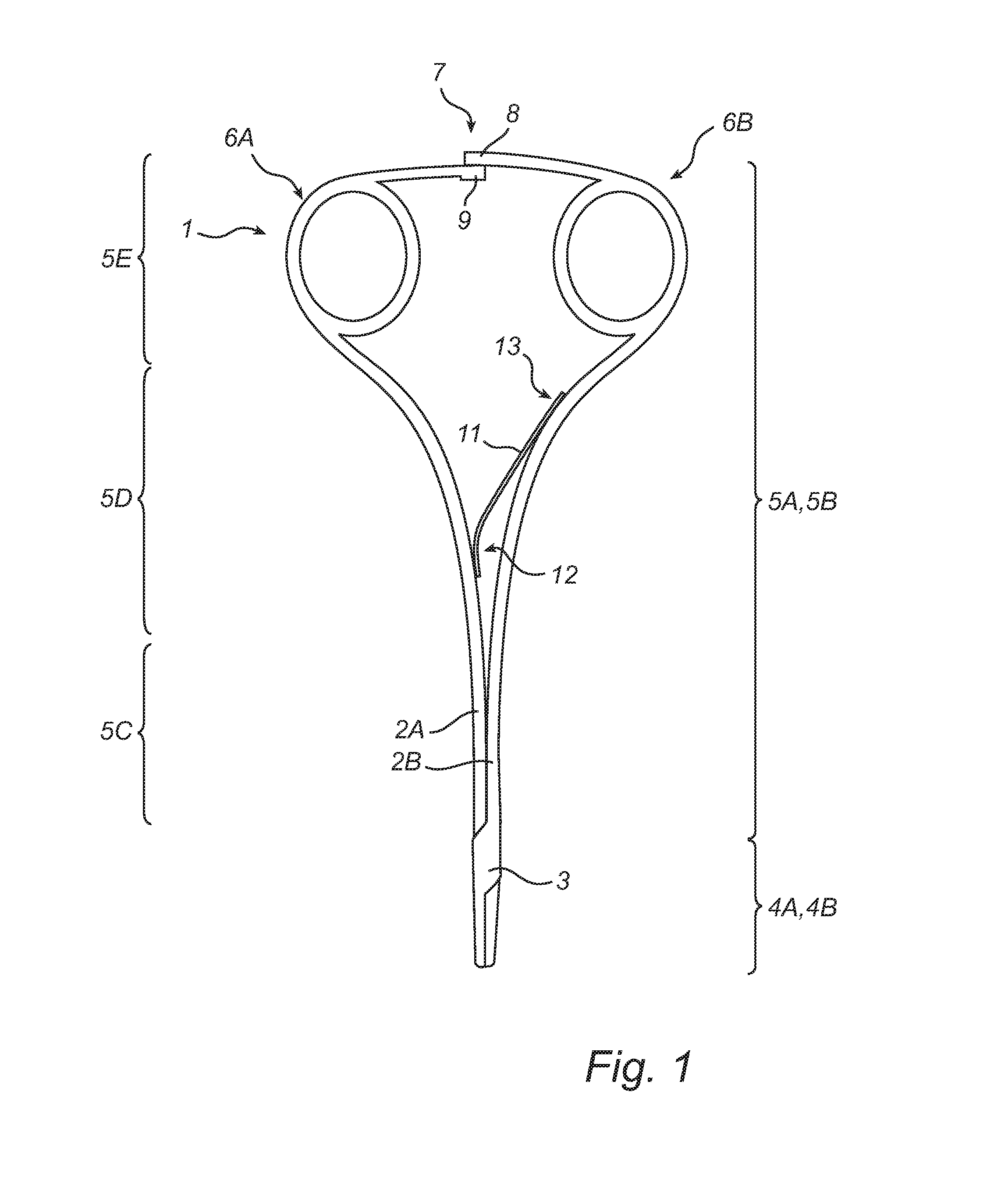
[0022]The invention will be described below with reference to a needle holder. The inventive concept can, however, be applied to other types of surgical devices, such as hemostatic forceps. FIG. 1 shows a needle holder 1 for holding surgical needles. The needle holder 1 has a basic design which is similar to that of a pair of scissors or pliers. The needle holder 1 comprises two legs 2a, 2b each having a first part 4a, 4b and a second part 5a, 5b. The legs are pivotably connected by a fulcrum 3, such as a pin extending perpendicular to the plane of the needle holder, intermediate the first part 4a, 4b and the second part 5a, 5b of the legs 2a, 2b. The legs 2a, 2b generally extend at each side of a symmetry plane parallel with the pin 3 so that the legs 2a and 2b are substantially mirror shapes of each other in the symmetry plane. The plane of the needle holder is perpendicular to the symmetry plane.

[0023]The first part 4a, 4b of the legs 2a, 2b comprises engagement members such as j...


PUM


Abstract

The present invention relates to a surgical device comprising first (2a) and second (2b) legs pivotally connected at a fulcrum (3) arranged between first (4a, 4b) and second (5a, 5b) parts of each leg. An engagement device is arranged at the first part of each leg, and a finger grip (6a, 6b) is arranged at the second part of each leg. The legs are arranged at each side of a symmetry plane through the fulcrum in a substantially mirror arrangement. The second part of each leg extends from the fulcrum in a first portion having an increased distance to the symmetry plane and in a second portion comprising the finger grips. Each finger grip is connected to the second portion of each leg at a connection point in which a centre of the finger grip is positioned closer to the symmetry plane than the connection point.

Description

FIELD OF THE INVENTION[0001]The present invention relates to a surgical device comprising a first leg and a second leg pivotally connected at a fulcrum arranged between a first part and a second part of each leg; an engagement device arranged at the first part of each leg for engagement with an object, such as tissue or a surgical needle; a finger grip in the form of a substantially closed loop arranged at the second part of each leg; the legs being arranged in a plane which is perpendicular to a symmetry plane through the fulcrum, whereby the legs are arranged at each side of the symmetry plane in a substantially mirror arrangement, the second part of each leg extending from the fulcrum in a first portion having an increased distance to the symmetry plane; and in a second portion comprising the finger grips.BACKGROUND OF THE INVENTION[0002]Within the medical field, it is very common to use different types of surgical devices such as forceps, both generally within medicine and more ...

Claims


Application Information

Patent Timeline
IPC IPC(8): A61B17/28A61B17/062
CPCA61B17/062A61B17/2833A61B17/2812A61B17/2841A61B2017/00424A61B2017/2845A61B17/0483
Inventor FRIMAND RONNOW, CARL-FREDRIK
Owner FRIMAND RONNOW CARL FREDRIK
Why Eureka
Try Eureka