
Ammunition magazine base pad retaining plate

a technology for retaining plates and ammunition magazines, which is applied in the field of ammunition magazines for firearms, can solve the problems of elongated front toe portion of the magazine base pad, difficult to grasp or remove the magazine that is stuck within the magazine cavity of the firearm, and catastrophic disassembly of the magazin

Active Publication Date: 2014-02-20
APEX TACTICAL SPECIALTIES
View PDF4 Cites 11 Cited by
  • Summary
  • Abstract
  • Description
  • Claims
  • Application Information

AI Technical Summary

Benefits of technology

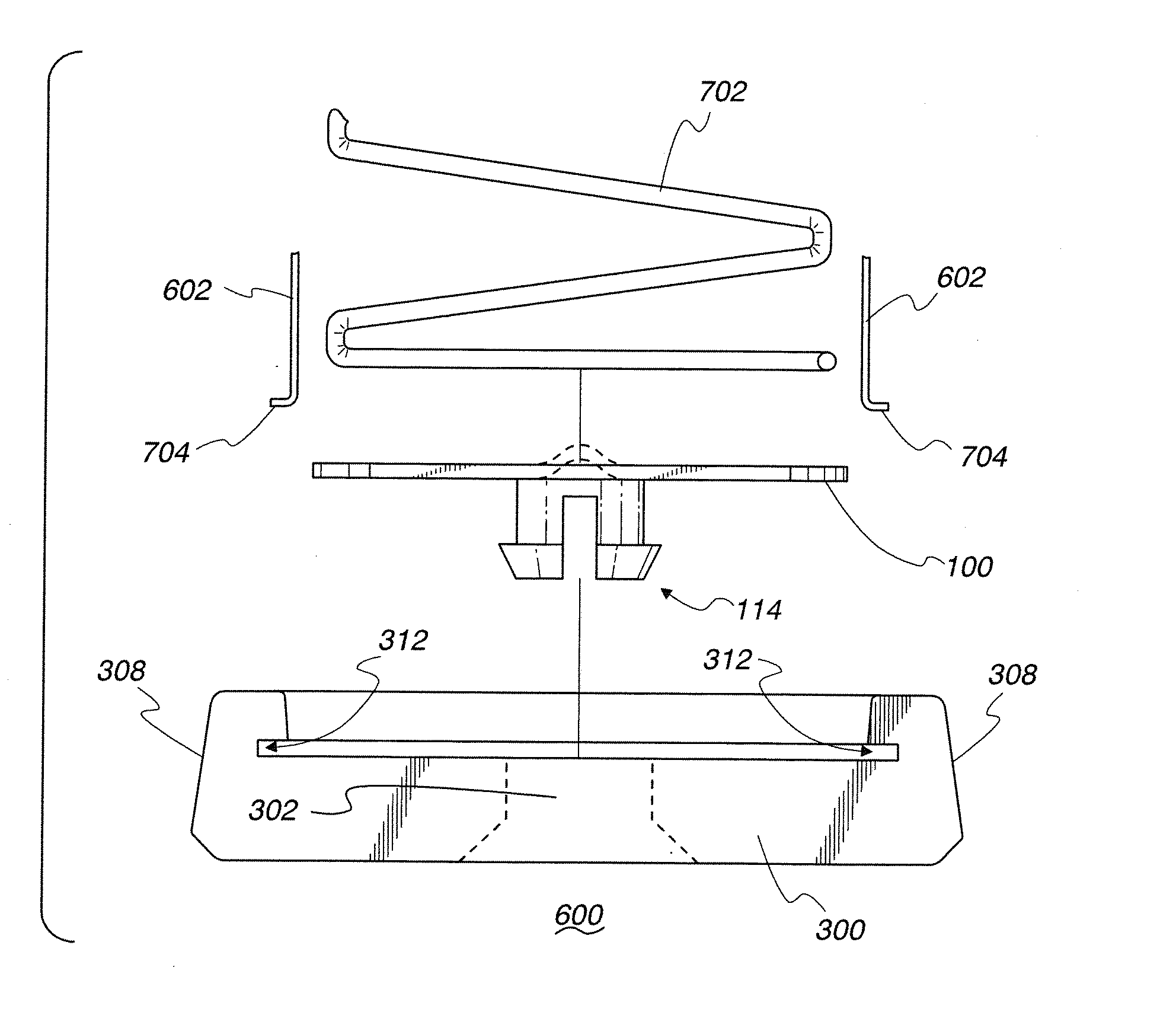
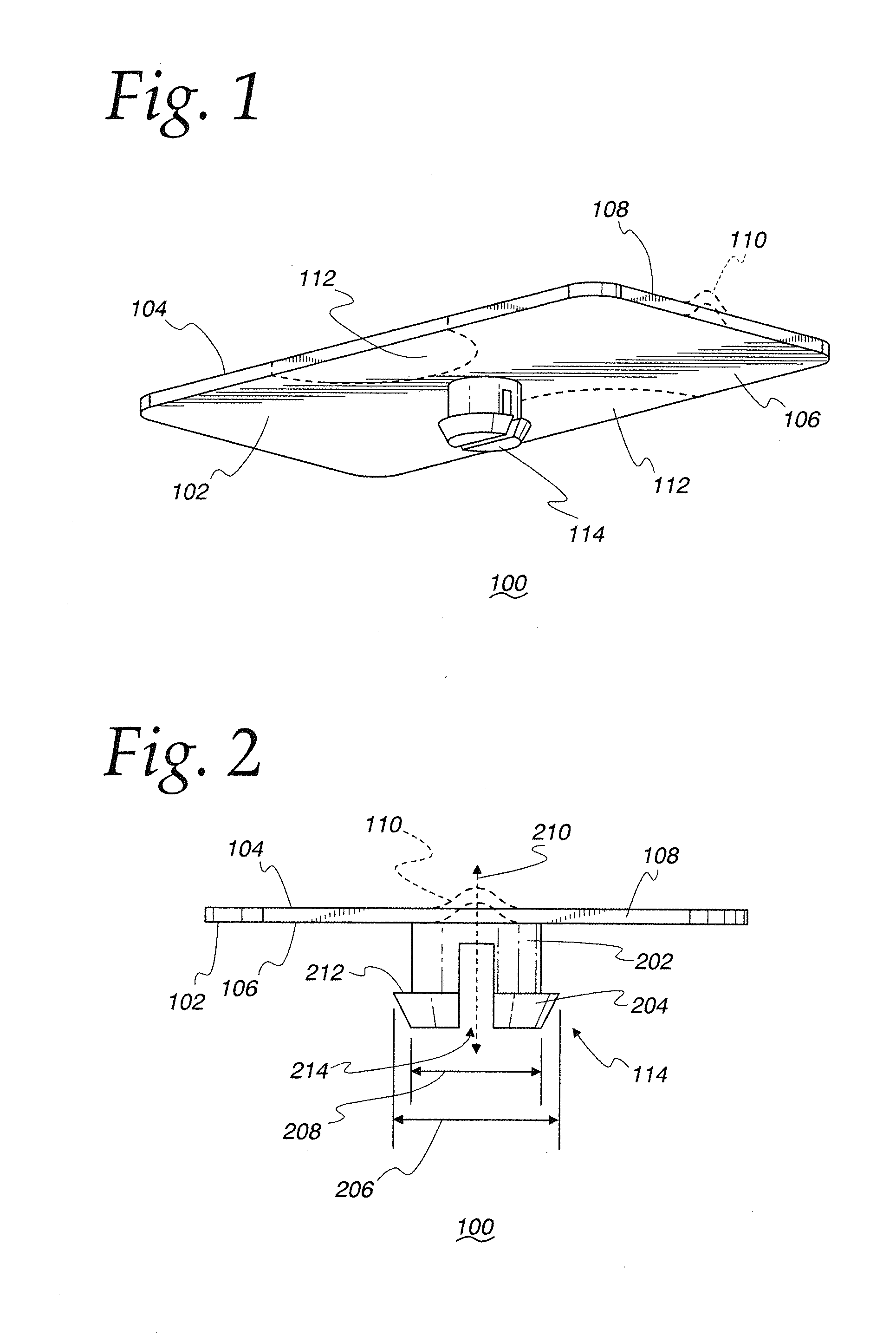
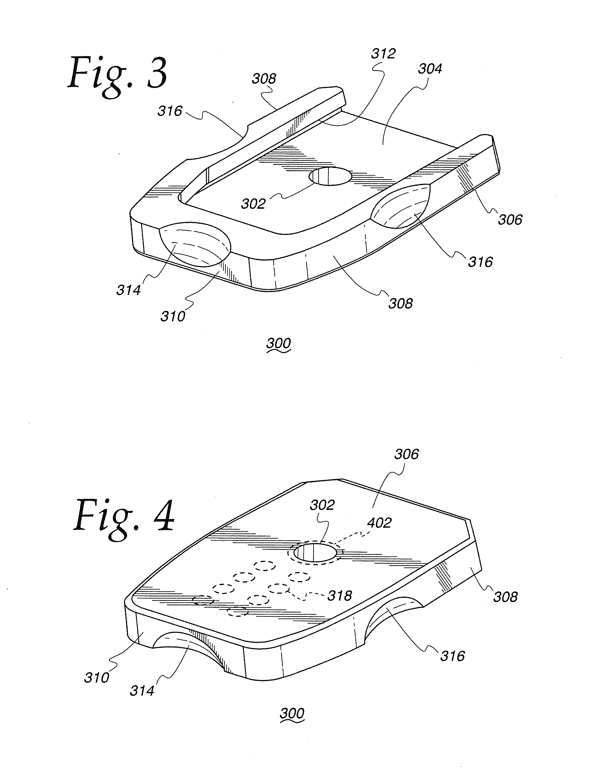
This patent describes a new invention for ammunition magazines. One version of the invention is a retaining plate that attaches to the base of the magazine and holds it securely. This plate has a protrusion that engages with holes on the magazine base pad. The retaining plate can be attached to a magazine housing and helps to ensure that the magazine stays in place. Another version of the invention includes a magazine base pad with a through-hole and special recesses on its front edge. The base pad is designed to fit snugly with the retaining plate and help stabilize the magazine. These features improve the reliability and performance of ammunition magazines.

Problems solved by technology

The physical interference between the protrusion and the walls of the through-hole in turn keep the magazine base pad from sliding off the magazine housing.
With these known configurations, a sharp blow to the magazine (either from forceful insertion into the magazine cavity or dropping the magazine) can dislodge the protrusion from the through-hole allowing the magazine base pad to slide off the magazine housing resulting in catastrophic disassembly of the magazine.
This makes it difficult to grasp or remove a magazine that is stuck within the magazine cavity of the firearm.
Further, such a configuration results in an elongated front toe portion of the magazine base pad.
This increases the likelihood that the magazine can catch on surfaces (such as other magazines or fingers) when extracting another magazine stored on a user's body in close proximity (i.e., in a pouch or magazine carrier).
Moreover, the longer toe can inhibit proper palm indexing of the magazine for users with smaller hands.

Method used


Image

  • Ammunition magazine base pad retaining plate
  • Ammunition magazine base pad retaining plate
  • Ammunition magazine base pad retaining plate

Examples


Embodiment Construction

[0024]The following description is not to be taken in a limiting sense, but is made merely for the purpose of describing the general principles of exemplary embodiments. The scope of the invention should be determined with reference to the claims.

[0025]Reference throughout this specification to “one embodiment,”“an embodiment,” or similar language means that a particular feature, structure, or characteristic described in connection with the embodiment is included in at least one embodiment of the present invention. Thus, appearances of the phrases “in one embodiment,”“in an embodiment,” and similar language throughout this specification may, but do not necessarily, all refer to the same embodiment.

[0026]Furthermore, the described features, structures, or characteristics of the invention may be combined in any suitable manner in one or more embodiments. In the following description, numerous specific details are provided to provide a thorough understanding of embodiments of the inven...


PUM

PropertyMeasurementUnit
distanceaaaaaaaaaa
angleaaaaaaaaaa
angleaaaaaaaaaa

Abstract

An ammunition magazine base pad retaining plate is provided with a protrusion including a shaft portion, a flange portion having a lager cross sectional diameter than the shaft portion, and a longitudinal slot to allow lateral compression. When attached to a magazine base pad in a magazine assembly, the configuration of the base pad retaining plate eliminates the possibility that the base pad retaining plate will disengage from the base pad resulting in catastrophic disassembly of the ammunition magazine.

Description

BACKGROUND OF THE INVENTION[0001]1. Field of the Invention[0002]The present invention relates generally to firearms, and more specifically to ammunition magazines for firearms.[0003]2. Discussion of the Related Art[0004]Many firearms utilize ammunition magazines to hold ammunition to be loaded into the firing chamber of the firearm and eventually fired. Specifically, handguns, and particularly semi-automatic handguns, often house an ammunition magazine in a cavity in the handle or grip portion. With such a configuration, the magazine is generally inserted upward into the cavity via an opening on the bottom surface of the firearm handle.[0005]Often, ammunition magazines will include a magazine base pad attached to the lower portion of the magazine housing. As is understood in the art, the magazine base pad provides a surface external to the magazine cavity of the firearm that allows a user to interface with the magazine. Amongst other benefits, this allows a user to quickly orient th...

Claims


Application Information

Patent Timeline
Patent Type & Authority Applications(United States)
IPC IPC(8): F41A9/61B23P23/00
CPCF41A9/65Y10T29/49716
Inventor LEE, RANDALL M.
Owner APEX TACTICAL SPECIALTIES
Learn More