
Trigger device for mobile computing device

a mobile computing and trigger technology, applied in the direction of mechanical control devices, pulse techniques, instruments, etc., can solve the problems of quality, efficiency, reliability, safety, ergonomics, cost effectiveness of triggers, quality, efficiency, reliability,

Inactive Publication Date: 2014-02-20
INTERMEC IP
View PDF6 Cites 735 Cited by
  • Summary
  • Abstract
  • Description
  • Claims
  • Application Information

AI Technical Summary

Benefits of technology

This patent is about a mobile computing device that can be triggered mechanically to activate various functions. The device has a trigger device attached to it, which generates a specific vibration pattern when activated. The device has a trigger interface that detects and converts the vibration pattern into an electrical signal pattern. The device's processor then acts on the signal pattern to perform the desired function, such as scanning or RFID reading. The patent also describes the trigger interface and the various techniques used to detect and decode the vibration pattern. The mobile computing device can be in various forms, such as a candy bar or clamshell, and the trigger device can be a removable part of the device. The patent also mentions that the trigger device can have multiple parts and the mechanical vibration pattern can include multiple bits of data. The invention allows for convenient and quick activation of various functions on a mobile computing device using a simple trigger device.

Problems solved by technology

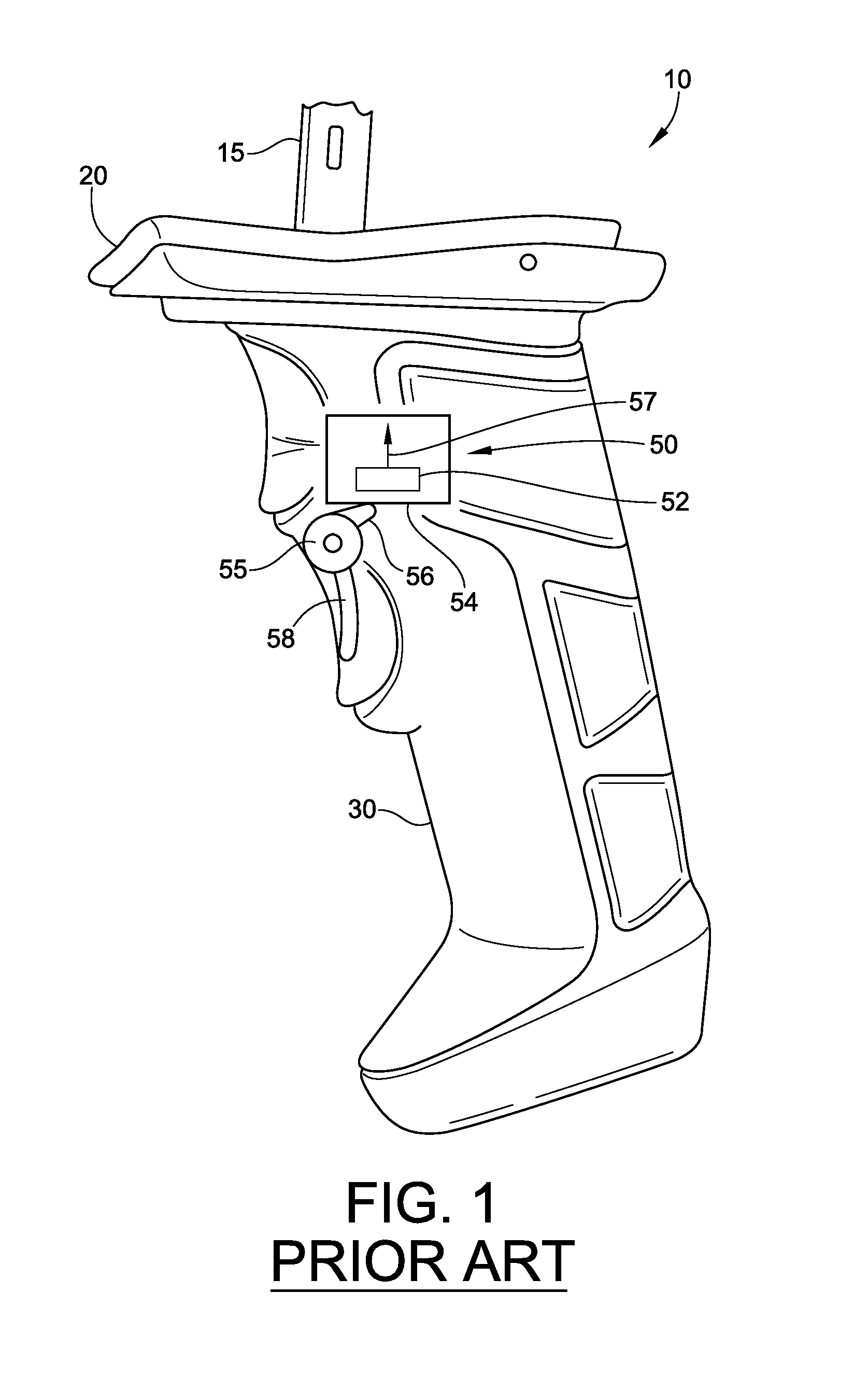
One set of limitations placed on this demand is the quality, efficiency, reliability, safety, ergonomics, and cost effectiveness of the trigger.
The set of design limitations of quality, efficiency, reliability, safety, ergonomics, and cost effectiveness have given general mobile computing devices many form factors.

Method used


Image

  • Trigger device for mobile computing device
  • Trigger device for mobile computing device
  • Trigger device for mobile computing device

Examples


Embodiment Construction

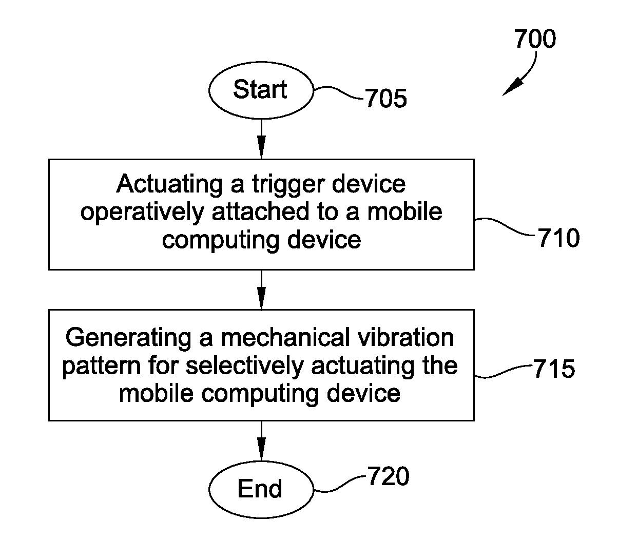
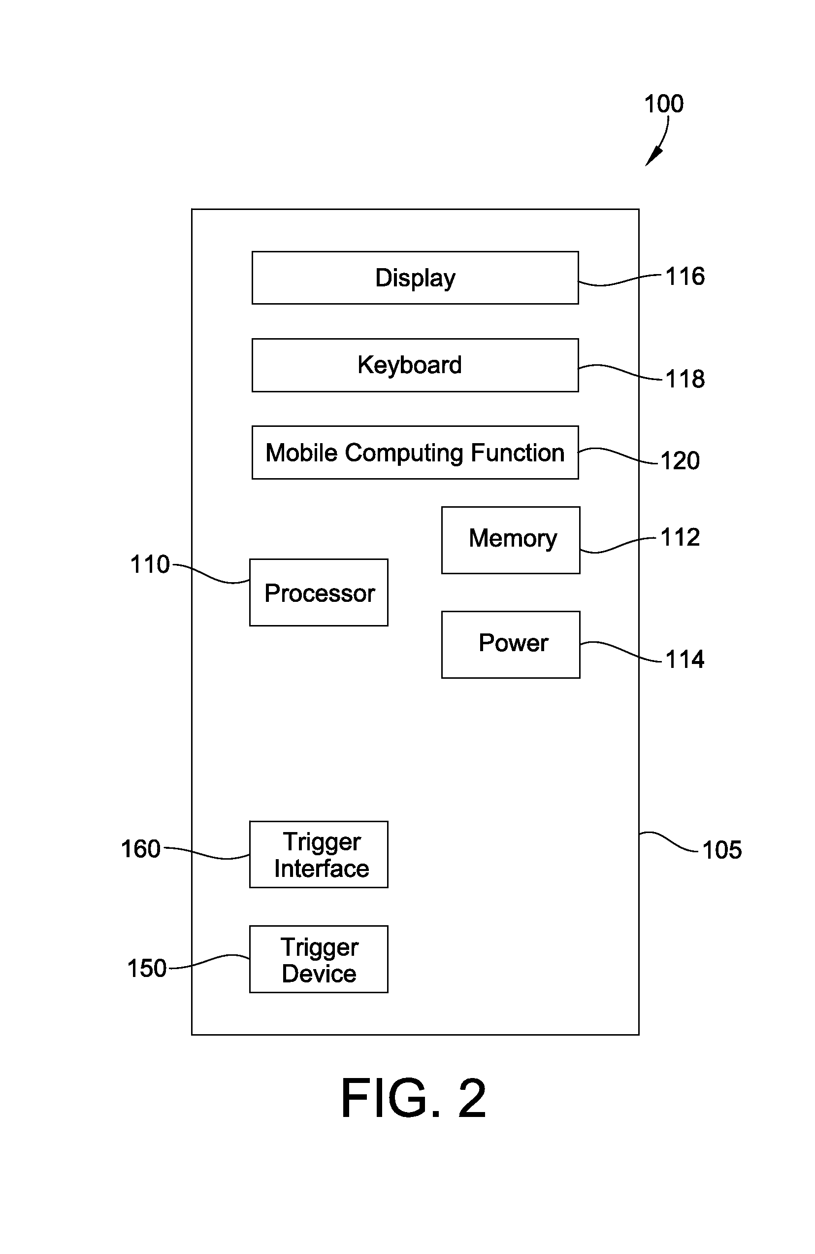
[0046]A mobile computing device is disclosed. The mobile computing device includes a first processor. A trigger device operatively attached to the mobile computing device is configured to generate a mechanical vibration pattern for selectively actuating the mobile computing device. A trigger interface is configured to detect and convert the mechanical vibration pattern into an electrical signal pattern. The first processor is configured to actuate a mobile computing function depending on the mechanical vibration pattern generated by the trigger device in response to the electrical signal pattern. In an illustrative example, the frequencies of the mechanical vibrations are in the sub-sonic to ultrasonic range.

[0047]In an illustrative embodiment, the trigger interface may include an accelerometer device. Illustratively, the conversion of the mechanical vibration pattern includes decoding the mechanical vibration pattern into mechanical vibration components.

[0048]In another embodiment,...


PUM


Abstract

A mobile computing device includes a processor and a trigger device operatively attached to the mobile computing device and configured to generate a mechanical vibration pattern for selectively actuating the mobile computing device. A trigger interface, illustratively an accelerometer, is configured to convert the mechanical vibration pattern into an electrical signal pattern. The processor is configured to actuate a mobile computing function depending on the mechanical vibration pattern generated by the trigger device. A table of properties stored in memory correlates the mechanical vibration generated by the trigger device with a specific mobile computing function. The trigger device may include a plurality of trigger parts; and the mechanical vibration pattern generated by the trigger device may include multiple bits of data generated by the plurality of trigger parts. The mobile computing device may be in a candy bar, clam shell, or other form factor and may include a removable handle.

Description

TECHNICAL FIELD[0001]The present disclosure relates to mobile computing devices and more particularly to a trigger device for mobile computing applications.BACKGROUND[0002]High demand exists for mobile computing devices that can be used anywhere, anytime. One set of limitations placed on this demand is the quality, efficiency, reliability, safety, ergonomics, and cost effectiveness of the trigger.[0003]A trigger may be a lever or button pushed by the finger or by some other external mechanism to activate a function. However, a trigger is not limited to a finger or other external activation. More broadly speaking, a trigger may also be located internally to the mobile computing device such as a circuit that initiates the action of another component. Hence, triggers may be external triggers or internal triggers depending on the design.[0004]Triggers play an important role in the use of a mobile computing device. These conventional mobile computing devices include a handheld terminal, ...

Claims


Application Information

Patent Timeline
Patent Type & Authority Applications(United States)
IPC IPC(8): H03K17/94
CPCH03K17/94G05G1/02G06F3/016G06F3/0338G06F3/0346G06F3/0362G05G9/047
Inventor KOHTZ, ROBERT A.AUSTIN, RICKEYCOOK, JOSEPH
Owner INTERMEC IP
Learn More