Process cartridge and image forming apparatus

a technology of image forming apparatus and process cartridge, which is applied in the direction of electrographic process apparatus, optics, instruments, etc., can solve the problems of development roller not being properly in contact with the electrophotographic photosensitive drum, increasing etc., to increase the amount of load, increase the amount of pressure, and increase the strength

Inactive Publication Date: 2014-02-20
CANON KK
View PDF4 Cites 25 Cited by
  • Summary
  • Abstract
  • Description
  • Claims
  • Application Information

AI Technical Summary

Benefits of technology

[0006]However, the conventional structural solutions, such as those described above, to the problem suffer from the following problems. That is, when a development roller is placed in contact with an electrophotographic photosensitive drum, a process cartridge comes into contact with the electrical contacts of the main assembly of an electrophotographic image forming apparatus. Thus, if the amount of pressure applied to keep the development roller in contact with the electrophotographic photosensitive drum is small, it is liable that the friction between the process cartridge and the electrical contacts of the electrophotographic image forming apparatus prevents the development roller from remaining properly in contact with the electrophotographic photosensitive drum. Thus, in the case of the structural solutions such as those described above, the pressure applied to keep the development roller properly in contact with the photosensitive arum had to be substantial. However, increasing the amount of pressure between the development roller and electrophotographic photosensitive drum resulted in increase in the amount of load to which the mechanism for keeping the development roller and photosensitive drum separated from each other is subjected while the image forming apparatus was on standby. Thus, the mechanism for keeping the development roller and photosensitive drum separated from each other had to be increased in strength. The present invention was made in consideration of problems such as those described above. Thus, the primary object of the present invention is to provide a process cartridge, the image bearing member and developer bearing member of which are separable from each other, and which is more stable in the state of contact between the image bearing member and developer bearing member than any of the process cartridge in accordance with the prior art, and also, an image forming apparatus which is compatible with the process cartridge which is in accordance with the present invention.

Problems solved by technology

However, the conventional structural solutions, such as those described above, to the problem suffer from the following problems.
Thus, if the amount of pressure applied to keep the development roller in contact with the electrophotographic photosensitive drum is small, it is liable that the friction between the process cartridge and the electrical contacts of the electrophotographic image forming apparatus prevents the development roller from remaining properly in contact with the electrophotographic photosensitive drum.
However, increasing the amount of pressure between the development roller and electrophotographic photosensitive drum resulted in increase in the amount of load to which the mechanism for keeping the development roller and photosensitive drum separated from each other is subjected while the image forming apparatus was on standby.

Method used


Image

  • Process cartridge and image forming apparatus
  • Process cartridge and image forming apparatus
  • Process cartridge and image forming apparatus

Examples


embodiment 1

[0032]First, the first preferred embodiment of the present invention is described.

(General Structure of Image Forming Apparatus)

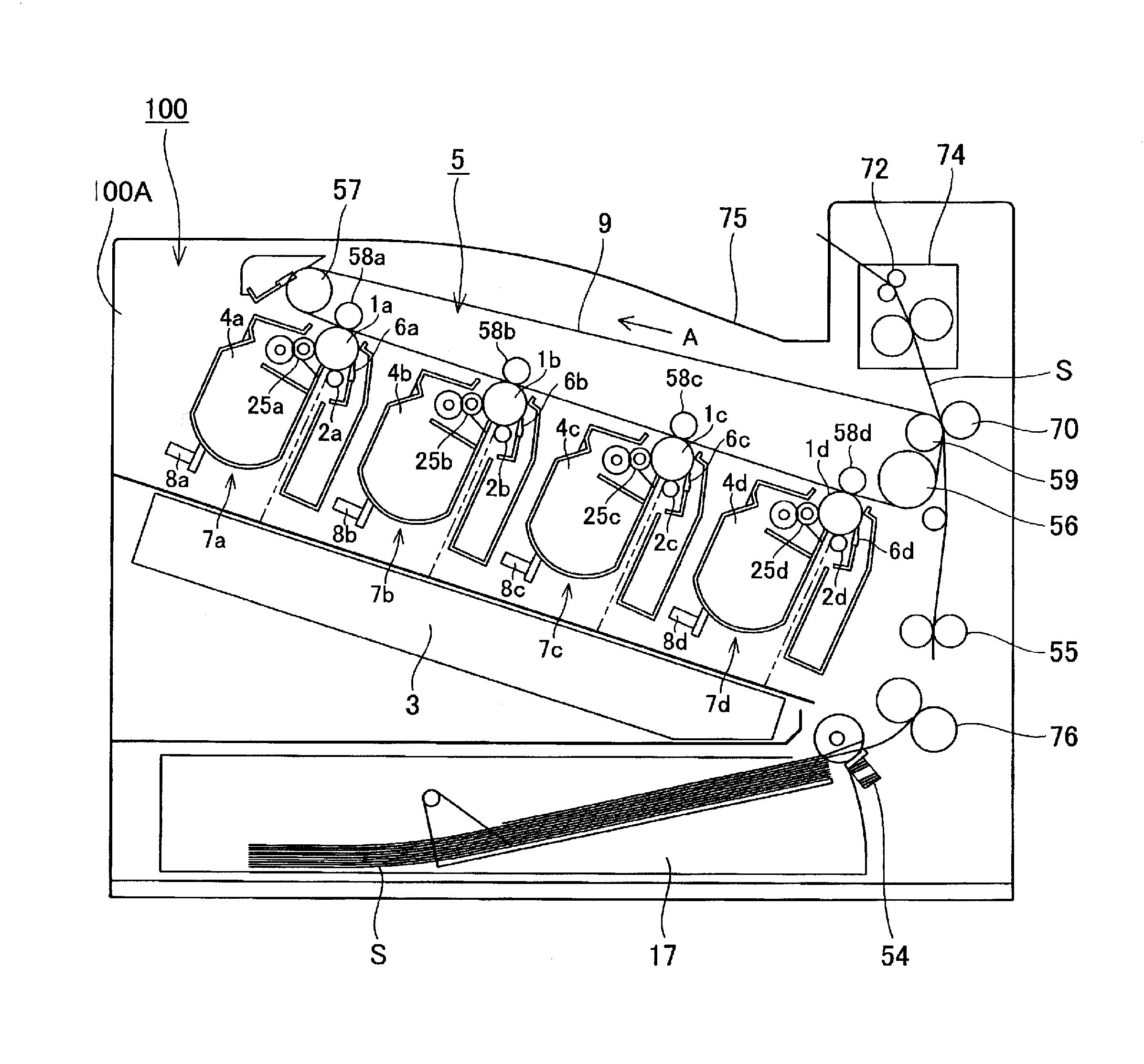
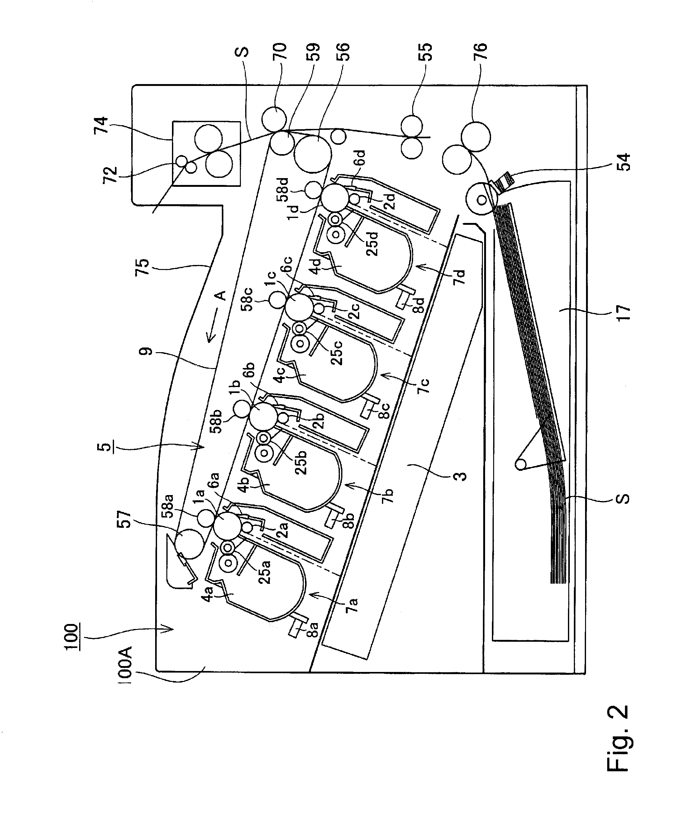
[0033]First, referring to FIG. 2, the overall structure of the electrophotographic image forming apparatus 100 (which hereafter will be referred to simply as image forming apparatus) in this embodiment.

[0034]FIG. 2 is a schematic sectional view of the image forming apparatus 100 in this embodiment, and shows the general structure of the apparatus. The image forming apparatus 100 employs four process cartridges 7 (7a, 7b, 7c, and 7d), which are removably mountable in the main assembly of the apparatus 100 with the use of a process cartridge mounting member (unshown), as shown in FIG. 2. Referring to FIG. 2, the process cartridges 7 (7a, 7b, 7c, and 7d) are positioned in the main assembly 100A of the image forming apparatus 100 (which hereafter will be referred to simply as apparatus main assembly 100A) in parallel at a preset angle relative to the horizontal...

embodiment 2

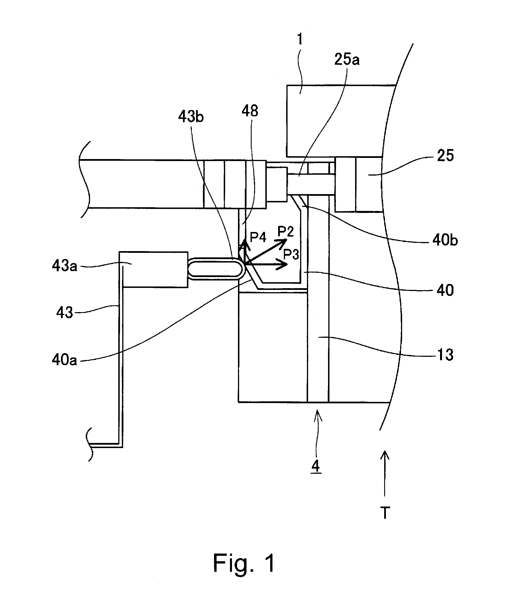
[0082]Next, referring to FIG. 16, the second embodiment of the present invention is described. The components, portions, and the like, of the image forming apparatus and process cartridge in this embodiment, which are similar to the counterparts in the first embodiment are given the same referential codes as those given to the counterparts in the first embodiment, and will not be described here. FIG. 16 is a schematic sectional view of the electrical contacts of the process cartridge 7, electrical contacts of the apparatus main assembly 100A, and their adjacencies in this embodiment when the development unit 4 is in the separation position.

[0083]Referring to FIG. 16, the primary characteristic feature of this embodiment is that when the development unit 4 is in the separation position, that is, the position in which the development roller 25 is kept separated from the photosensitive drum 1, the compression spring 43a of the development bias contact 43 is in contact with the electric...

embodiment 3

[0086]Next, referring to FIG. 17, the third preferred embodiment of the present invention is described. The components, parts, etc. of the image forming apparatus and process cartridge in this embodiment, which are similar to the counterparts in the preceding embodiments are given the same referential codes as those for the counterparts, and are not described. FIG. 17 is a schematic sectional view of the electrical contacts of the process cartridge 7 and the electrical contacts of the apparatus main assembly 100A in this embodiment, when the development unit 4 is in the separation position.

[0087]The primary characteristic feature of this embodiment is that when the development unit 4 is in the separation position, that is, the position in which the development roller 25 is kept separated from the photosensitive drum 1, the compression spring 43a of the development bias contact 43 is not in contact with the process cartridge 7, as shown in FIG. 17. More specifically, the side cover 4...


PUM


Abstract

A process cartridge is detachably mountable to a main assembly of an image forming apparatus. The process cartridge includes a first unit provided with an image bearing member and a second unit that is provided with a developer carrying member for carrying a developer, with the second unit being connected with the first unit so as to be movable between a contact position in which the developer carrying member is contacted with that image bearing member and a spacing position in which the developer carrying member is spaced from the image bearing member. The second unit includes a recess or opening into which a main assembly electrical contact provided in the main assembly of the apparatus to apply a voltage to the process cartridge when the process cartridge is mounted to the main assembly of the apparatus and second unit is positioned in the spacing position.

Description

[0001]This application is a divisional of application Ser. No. 13 / 096,467, filed Mar. 8, 2011.FIELD OF THE INVENTION AND RELATED ART[0002]The present invention relates to an image forming apparatus having a function to form an image on recording medium such as a sheet of paper. It relates also to a process cartridge which is removably mountable in an image forming apparatus.[0003]A process cartridge has long been used in the field of an electrophotographic image forming apparatus. A process cartridge is removably mountable in the main assembly of an electrophotographic image forming apparatus. It comprises: an electrophotographic photosensitive drum; one or more means for processing the photosensitive drum; and a shell (cartridge) in which the electrophotographic photosensitive drum and processing means are integrally placed. A process cartridge makes it possible for a user to maintain an image forming apparatus without relying on a service person. Thus, it can substantially increas...

Claims


Application Information

Patent Timeline
Patent Type & Authority Applications(United States)
IPC IPC(8): G03G21/18
CPCG03G21/1803G03G21/1871G03G15/80G03G21/1652G03G2221/1654G03G2221/166
Inventor CHADANI, KAZUOKOYAMA, OSAMUGOFUKU, SHUICHI
Owner CANON KK
Why Eureka
Try Eureka