Apparatus and method for venting gas from a liquid

a technology of apparatus and liquid, which is applied in the direction of liquid degasification, water supply installation, separation process, etc., can solve the problems of clogging the filter and reducing the ability of gas (e.g., air) to exit through the filter

a technology of apparatus and liquid, which is applied in the direction of liquid degasification, water supply installation, separation process, etc., can solve the problems of clogging the filter and reducing the ability of gas (e.g., air) to exit through the filter

US20140052044A1Inactive Publication Date: 2014-02-20FRESENIUS MEDICAL CARE HLDG INC

Image

  • Apparatus and method for venting gas from a liquid
  • Apparatus and method for venting gas from a liquid
  • Apparatus and method for venting gas from a liquid

Examples


Embodiment Construction

[0015]A description of example embodiments of the invention follows.

Extracorporeal Circuit

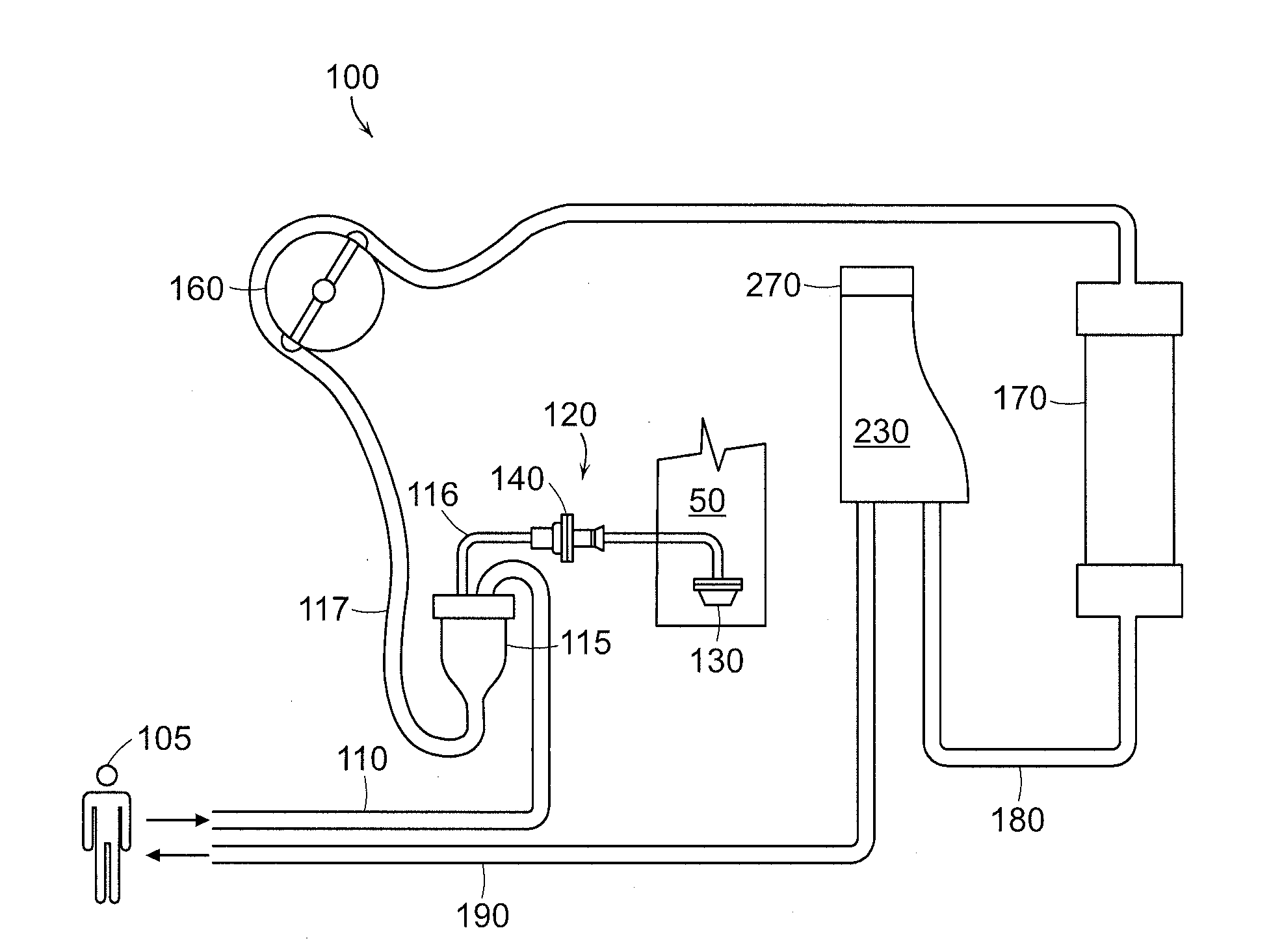
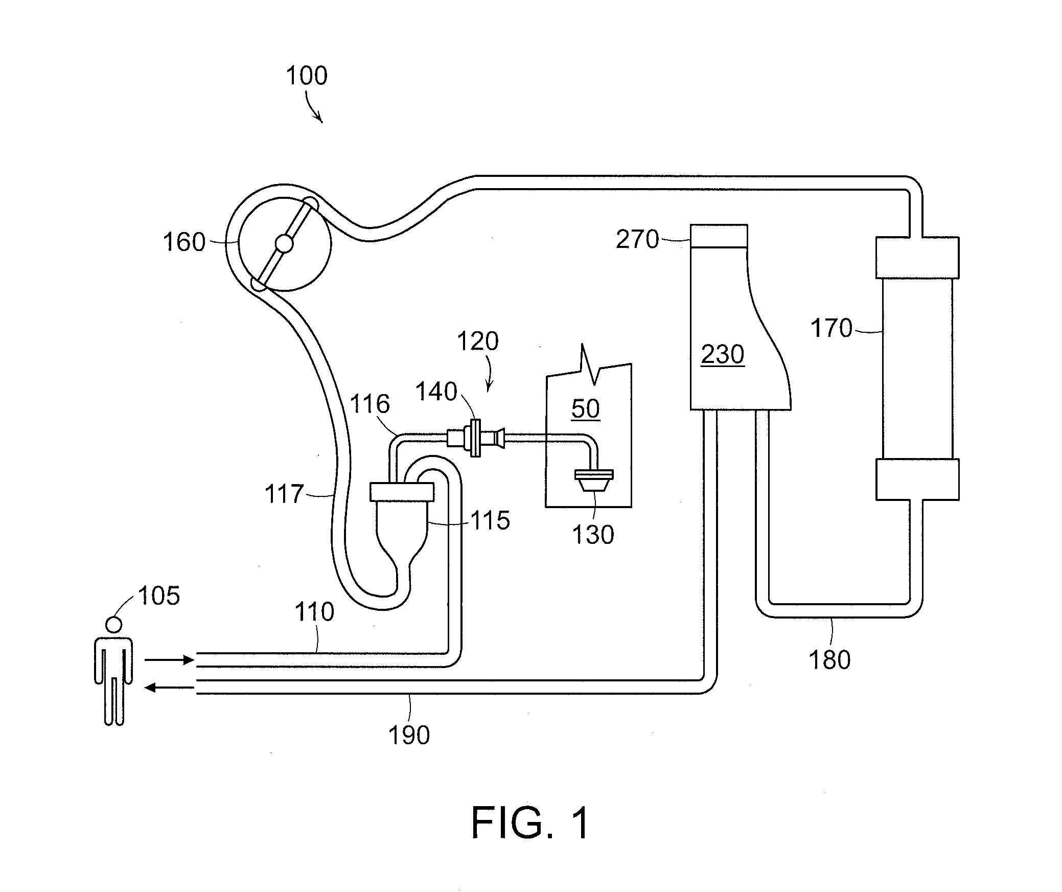
[0016]FIG. 1 illustrates a typical extracorporeal hemodialysis circuit 100, which includes tubing through which the blood flows and components for filtering and performing dialysis on the blood. Blood flows from a patient 105 through arterial tubing 110. After exiting the patient, blood drips into a drip chamber 115 where a connecting tube 116 from the drip chamber 115 attaches to an arterial pressure sensor assembly 120 that determines the pressure of the blood on the arterial side of the circuit 100.

[0017]A pump 160, such as a peristaltic pump, forces the blood to continue along the path through the circuit 100. After exiting the drip chamber 115, the blood then flows through tubing 117 to a dialyzer 170, which separates waste products from the blood. After passing through the dialyzer 170, the blood flows through venous tubing 180 towards a gas venting chamber 230 in which gas (e.g., air) in...


PUM

PropertyMeasurementUnit
densityaaaaaaaaaa
concentrationaaaaaaaaaa
hydrophobicaaaaaaaaaa

Abstract

The present invention relates to an apparatus and method for venting a gas from a liquid, which are applicable to a wide variety of medical liquid delivery systems. The apparatus includes level detectors, a clamp, and a control apparatus operably connected to the level detectors and the clamp. The method includes detecting whether liquid or gas is present at the level detectors, and opening and closing a clamp to vent gas.

Description

RELATED APPLICATION[0001]This application claims the benefit of U.S. Provisional Application No. 61 / 470,680, filed on Apr. 1, 2011.[0002]The entire teachings of the above application are incorporated herein by reference.BACKGROUND OF THE INVENTION[0003]Hemodialysis is the diffusive transfer of small solutes out of blood plasma by diffusion across a semi-permeable membrane. Dialysis proceeds due to a concentration gradient across the membrane such that solutes diffuse from a liquid having a higher concentration to a liquid having a lower concentration. Hemodialysis removes toxic substances and metabolic waste from the bloodstream using an extracorporeal circuit with components designed to perform ultrafiltration and diffusion on the blood. Before the blood is returned to the body, air bubbles are removed from the blood to inhibit embolisms.[0004]Gas venting chambers for hemodialysis systems have been disclosed in the art. For example, a conventional system is disclosed in U.S. Public...

Claims


Application Information

Patent Timeline
20 Feb 2014
Publication
US20140052044A1
IPC
A61M1/16; B01D19/00
CPC
B01D19/0063; A61M1/16; A61M1/3624; A61M1/3627; A61M2205/3382; A61M2205/3386; A61M2205/123; Y10T137/0318
Inventors
CRNKOVICH, MARTIN JOSEPH; WEAVER, COLIN