Belt driving apparatus and image forming apparatus
- Summary
- Abstract
- Description
- Claims
- Application Information
AI Technical Summary
Benefits of technology
Problems solved by technology
Method used
Image
Examples
embodiment 1
[0029]
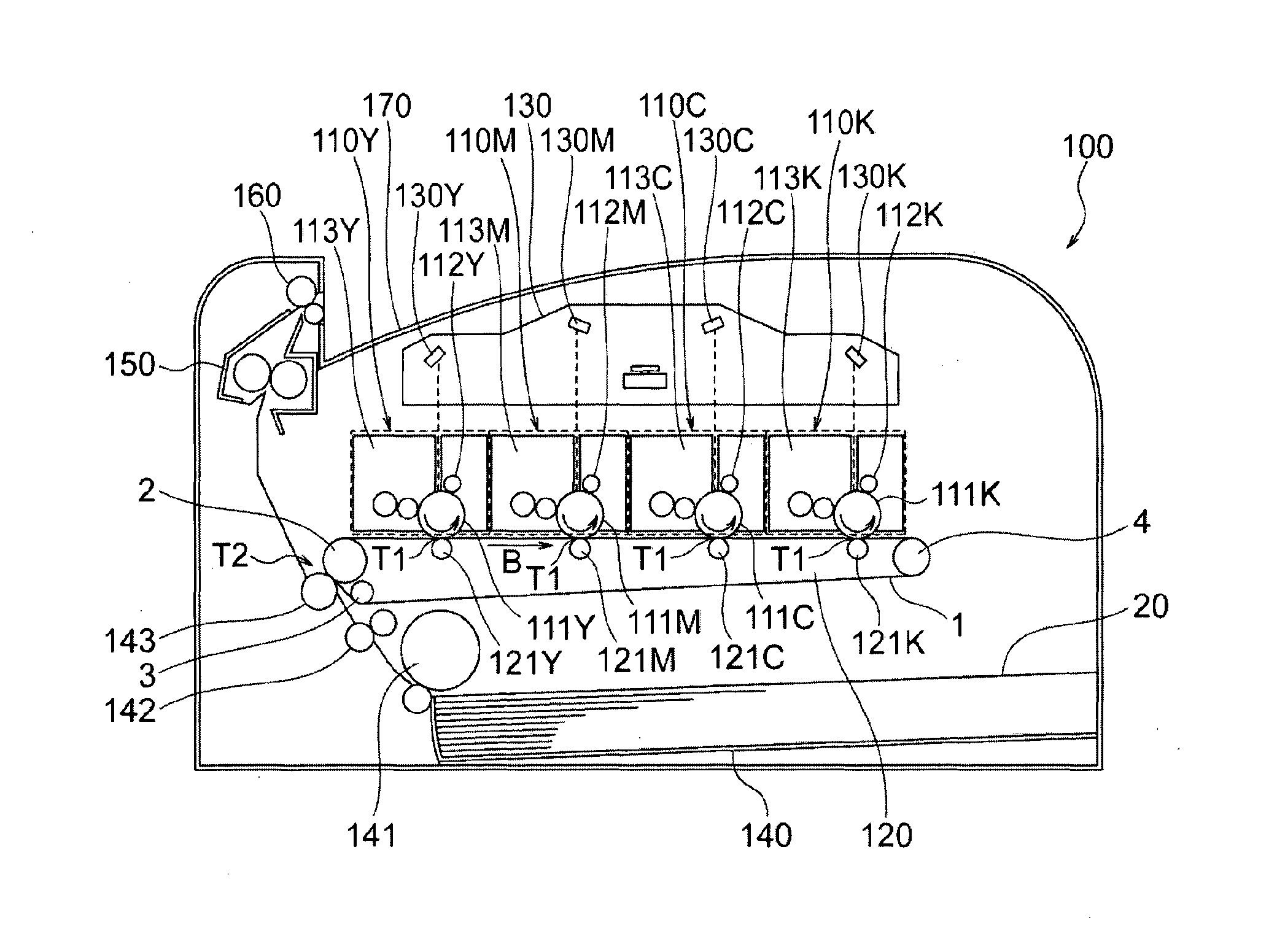
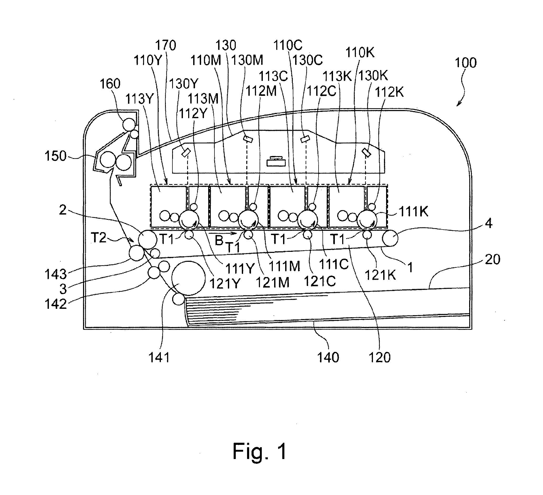
[0030]FIG. 1 is a schematic sectional view of a typical color image forming apparatus equipped with a belt driving unit, as an intermediary transfer unit, in accordance with the present invention, and shows the general structure of the apparatus. To begin with, the structure of the image forming apparatus 100 in this embodiment is described referring to FIG. 1. The image forming apparatus 100 can electrophotographically form an image on a sheet P of recording medium such as ordinary recording paper, OHP film, etc., in response to electrical signals sent from an external devices such as a personal computer connected to the image forming apparatus 100 in such a manner that information can be exchanged between the image forming apparatus and external devices.
[0031]The image forming apparatus 100 has multiple (four in this embodiment) image formation units 110Y, 110M, 110C and 110K, which form yellow, magenta, cyan and black monochromatic toner images, respectively. The image form...
embodiment 2
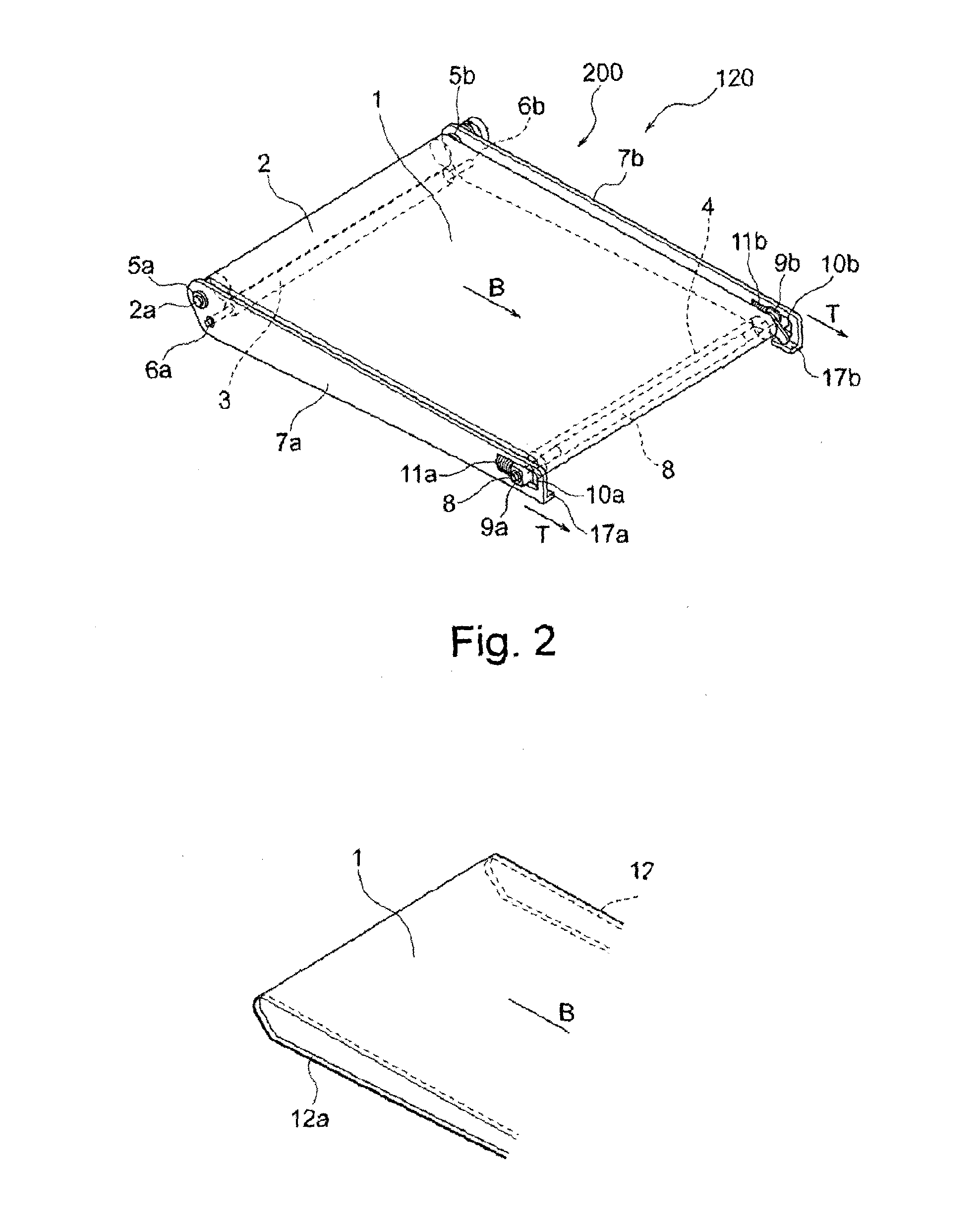
[0078]Next, referring to FIGS. 13 and 14, the invention is described with reference to another belt driving unit in accordance with the present invention, and an image forming apparatus equipped with this belt driving unit. In the following description of the second embodiment, the components, portions, etc., of the belt driving unit and image forming apparatus, which are the same in structure as the counterparts in the first embodiment are given the same referential codes as those given to the counterparts, and are not going to be described here. In the first embodiment, both the widthwise edge portions of the belt 1 were provided with ribs 12a and 12b, one for one. Further, both the lengthwise end portions of the tension roller 4 were provided with rollers 16a and 16b, one for one, having the rib contacting portion 16e, which corresponds to the ribs 12a or 12b, respectively.
[0079]In this embodiment, the belt driving unit is structured so that the belt 1 is made to tend to laterall...
embodiment 3
[0087]Next, referring to FIG. 15, the third embodiment of the present invention is described with reference to another belt driving unit in accordance with the present invention, and an image forming apparatus equipped with the belt driving unit. The components, portions, etc., of the belt driving unit and image forming apparatus, which are similar in structure as the counterparts in the first embodiment are given the same referential codes as those given to the counterparts, and are not going to be described here. In the first embodiment, the belt 1 was provided with the ribs 12a and 12b, which were attached next to the edges of the belt 1, one for one, and the lengthwise ends of tension roller 4 was provided with the rollers 16a and 16b, one for one, having the rib contacting portion 16e which corresponds in position to the rib 12a or 12b, respectively.
[0088]Further, the belt driving portion 200 was structured so that as the belt 1 shifts in its widthwise direction, only the rib 1...
PUM
 Abstract
Description
Claims
Application Information
 - R&D
- Intellectual Property
- Life Sciences
- Materials
- Tech Scout
- Unparalleled Data Quality
- Higher Quality Content
- 60% Fewer Hallucinations
Browse by: Latest US Patents, China's latest patents, Technical Efficacy Thesaurus, Application Domain, Technology Topic, Popular Technical Reports.
© 2025 PatSnap. All rights reserved.Legal|Privacy policy|Modern Slavery Act Transparency Statement|Sitemap|About US| Contact US: help@patsnap.com


