
Display apparatus

Inactive Publication Date: 2014-02-27
SAMSUNG DISPLAY CO LTD
View PDF4 Cites 25 Cited by
  • Summary
  • Abstract
  • Description
  • Claims
  • Application Information

AI Technical Summary

Benefits of technology

The present invention is about a display screen that reduces brightness differences between pixels. This prevents issues like vertical lines being perceived. This technology improves the overall quality of the display.

Problems solved by technology

Among the display devices, the liquid crystal display has a viewing angle inferior to that of the other display devices.

Method used


Image

  • Display apparatus
  • Display apparatus
  • Display apparatus

Examples


Embodiment Construction

[0038]Hereinafter, embodiments of the present invention will be explained in detail with reference to the accompanying drawings.

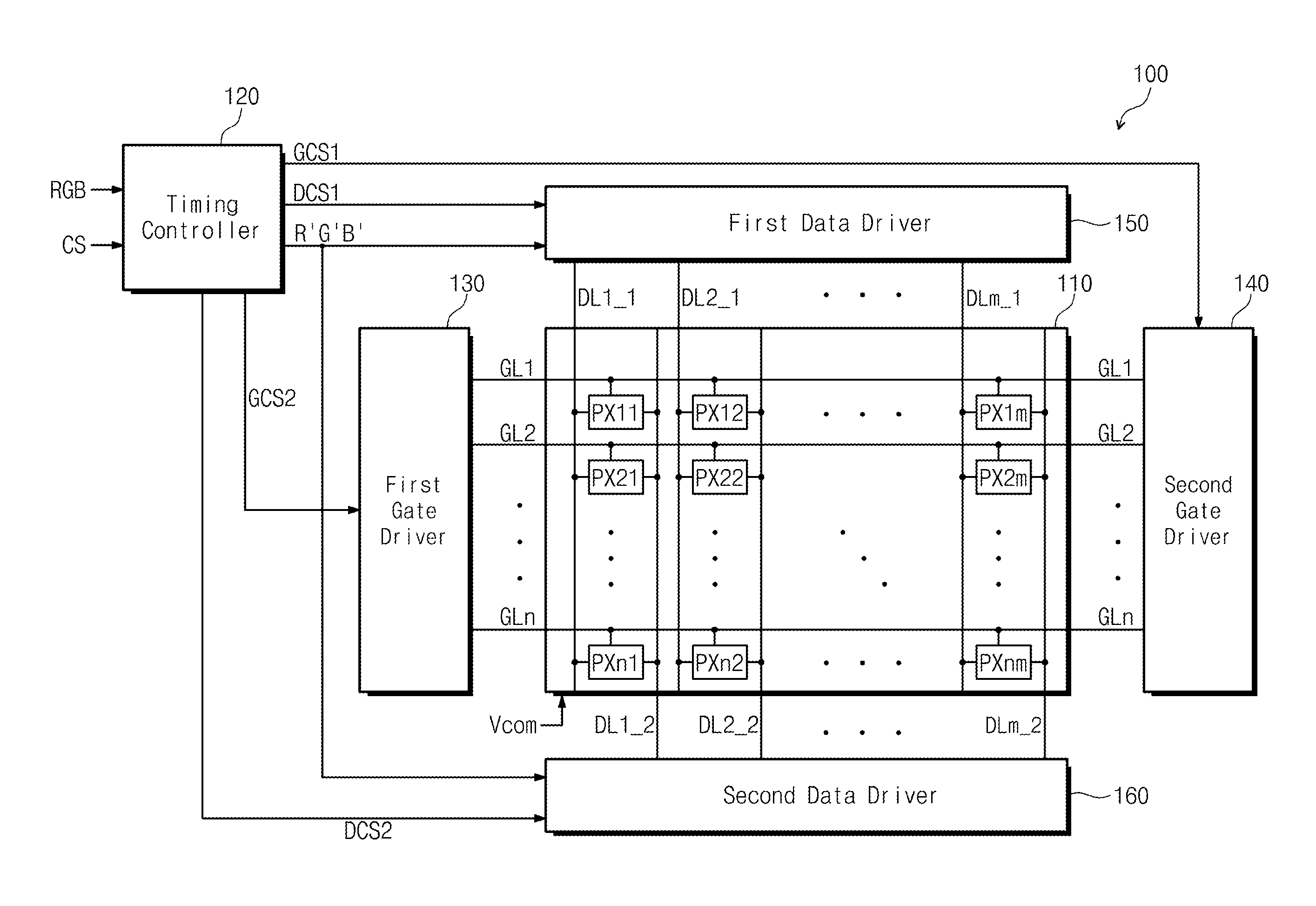
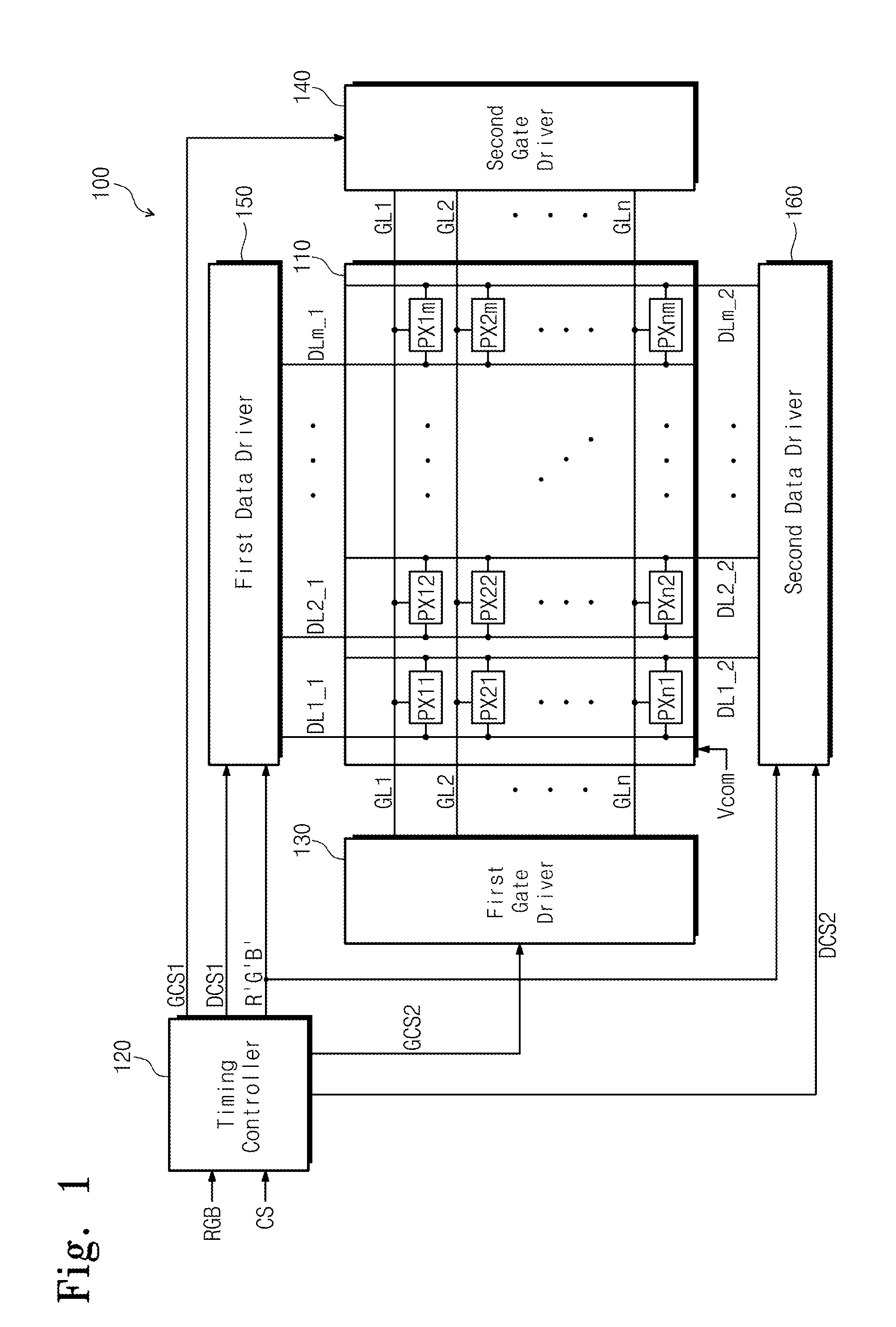
[0039]FIG. 1 is a block diagram showing a display apparatus according to an exemplary embodiment of the present invention.

[0040]Referring to FIG. 1, a display apparatus 100 includes a display panel 110, a timing controller 120, a first gate driver 130, a second gate driver 140, a first data driver 150, and a second data driver 160.

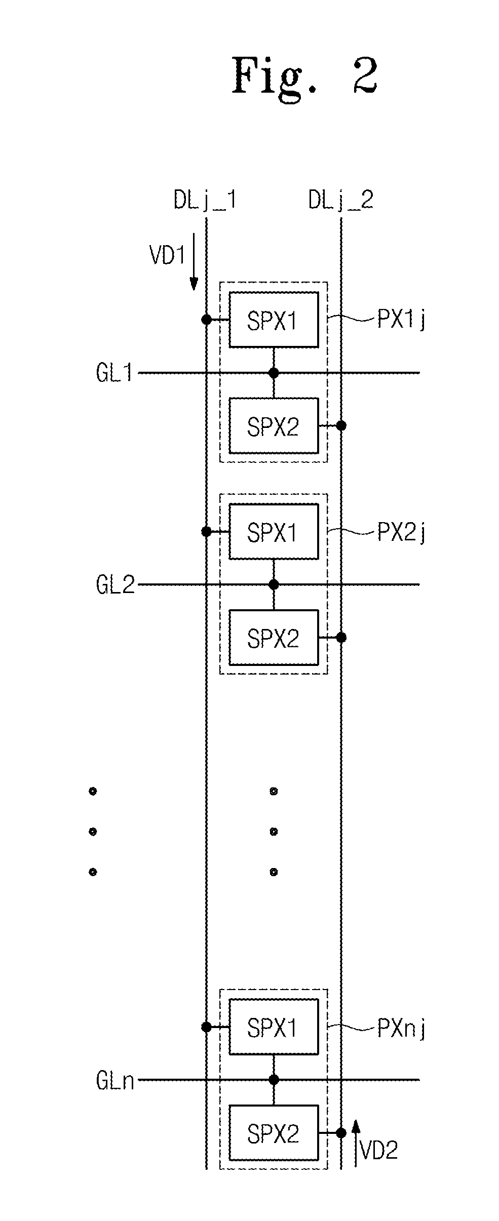
[0041]The display panel 110 includes a plurality of pixels PX11 to PXnm arranged in a matrix form, a plurality of gate lines GL1 to GLn each connected to pixels arranged in a corresponding row, and a plurality of data lines DL1—1, DL1—2, DL2—1, DL2—2, . . . , DLm-1, and DLm—2 each connected to the pixels arranged in a corresponding column. The data lines DL1—1, DL1—2, DL2—1, DL2—2, . . . , DLm-1, and DLm—2 cross the gate lines GL1 to GLn.

[0042]The data lines DL1—1, DL1—2, DL2—1, DL2—2, . . . , DLm-1, and DLm—2 include a plurality ...


PUM


Abstract

A display apparatus includes a plurality of pixels, each of the pixels including a high pixel and a low pixel, a first data driver disposed on a first side of the display panel and applying first data voltages to the high pixels through first data lines, a second data driver disposed on a second side opposite the first side of the display panel and applying second data voltages to the low pixels through second data lines, and a first gate driver formed on a third side of the display panel between the first side and the second side, and sequentially applying gate signals to the plurality of pixels connected to gate lines. The first data voltages are sequentially supplied to the high pixels from the first side of the display panel and the second data voltages are sequentially supplied to the low pixels from the second side of the display.

Description

CROSS-REFERENCE TO RELATED APPLICATION[0001]This U.S. non-provisional patent application claims priority under 35 U.S.C. §119 of Korean Patent Application No. 10-2012-0091490, filed on Aug. 21, 2012, the contents of which are hereby incorporated by reference.BACKGROUND[0002]1. Field of disclosure[0003]The present disclosure relates to a display apparatus. More particularly, the present disclosure relates to a display apparatus capable of reducing brightness difference.[0004]2. Description of the Related Art[0005]In recent years, various display devices, such as a liquid crystal display, an organic light emitting diode display, an electrowetting display device, an electrophoretic display device, etc., have been developed.[0006]In general, the display device includes pixels to display an image. The pixels receive gate signals through gate lines. The pixels receive data signals through data lines in response to the gate signals and display gray scales corresponding to the data signals....

Claims


Application Information

Patent Timeline
IPC IPC(8): G09G5/10G09G3/36
CPCG09G3/3607G09G5/10G09G3/3614G09G3/3648G09G3/3659G09G3/3688G09G2300/0447G09G2320/0233G09G3/36
Inventor JUNG, MEEHYELIM, SANG-UKBAE, JAESUNGYOU, BONGHYUN
Owner SAMSUNG DISPLAY CO LTD
Learn More