Contoured calcaneal plate and a percutaneous drill guide for use therewith

a calcaneal plate and contouring technology, applied in the field of less invasive fully contoured orthopedic implants, can solve the problems of plate displacement, large and relatively invasive surgery, and sensitive soft tissue displacemen

Active Publication Date: 2014-03-06
ORTHOHELIX SURGICAL DESIGNS
View PDF1 Cites 60 Cited by
  • Summary
  • Abstract
  • Description
  • Claims
  • Application Information

AI Technical Summary

Problems solved by technology

For some situations, these plates remain ideal; however, these prior art plates require a large and relatively invasive surgery and displacement of sensitive soft tissue to access the bone.

Method used


Image

  • Contoured calcaneal plate and a percutaneous drill guide for use therewith
  • Contoured calcaneal plate and a percutaneous drill guide for use therewith
  • Contoured calcaneal plate and a percutaneous drill guide for use therewith

Examples


Embodiment Construction

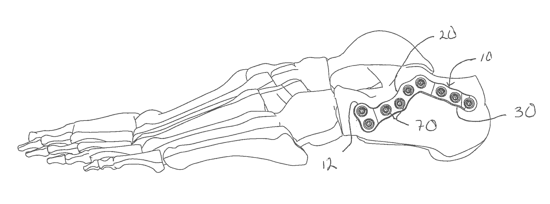
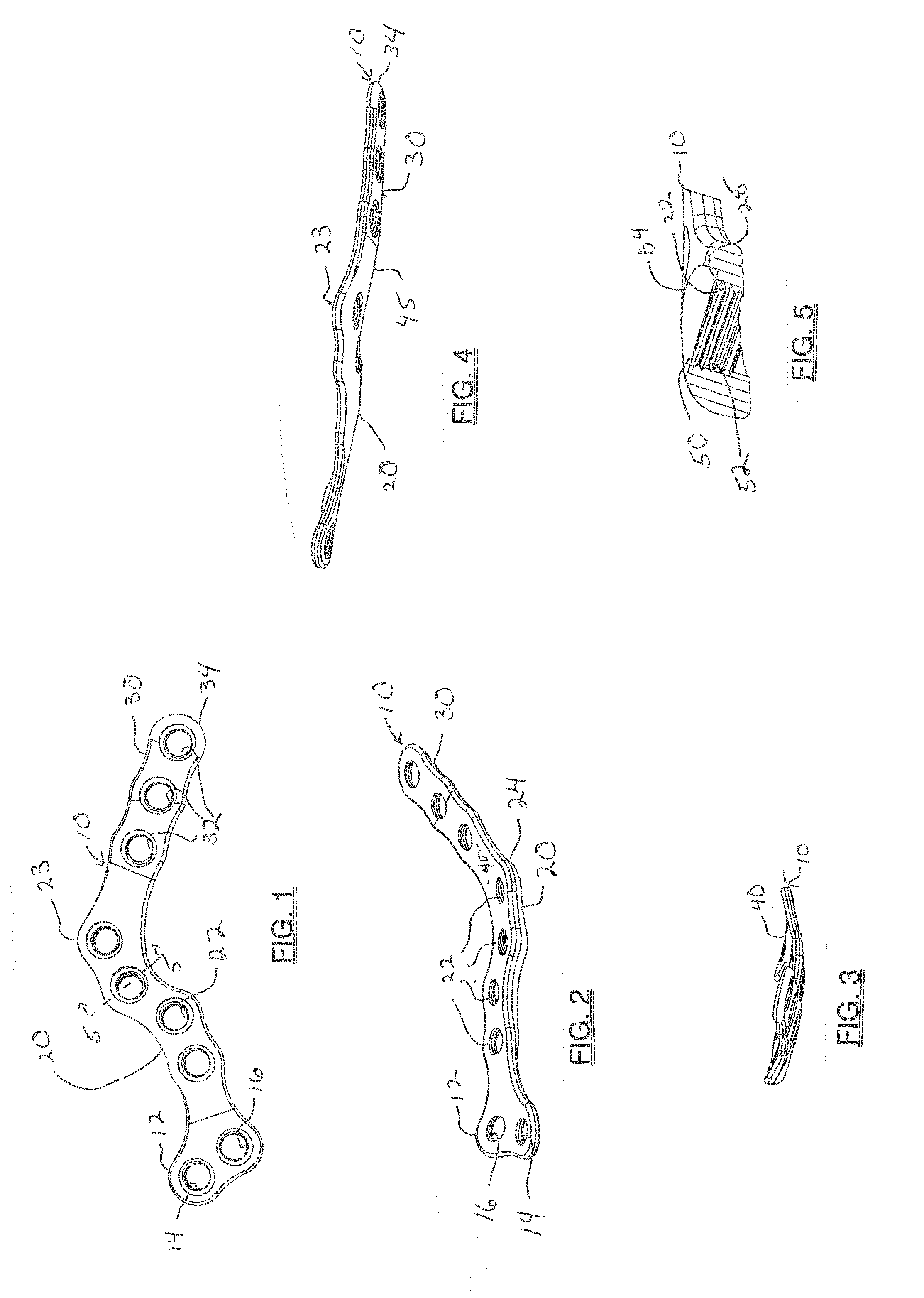
[0032]The implant of the present invention is a less invasive calcaneal plate shown from the top in FIG. 1 at 10. The plate 10 has an undulating profile which can be envisioned as an anterior tab 12 having an internally threaded superior and anterior locking hole 14 and relative to the first hole, an internally threaded inferior and posterior locking hole 16 which provide for multiplanar fixation, Attached to this is a posterior facet supporting section 20 which has a serpentine shape and a plurality of locking holes 22 (preferably four) where the profile of the plate section accommodates and supports the loading at the posterior facet, Further as may be viewed in FIG. 4, the superior most portion 23 of the posterior facet section 20 tapers in thickness and wraps inward in the direction of the bone facing surface so that the plate contouring in the Z direction accommodates a generalized shape of a calcaneus, and avoids edges that would provide places for soft tissue, and in particul...


PUM


Abstract

This invention provides a calcaneal plate implanted using a sinus tarsi approach and comprises an anterior section having two locking screw holes, an s-shaped posterior facet section having a four locking holes and which rounds toward the bone at both the inferior and superior edges and is reinforced at the superior edge, and a blade shaped posterior portion having three linearly aligned locking holes and terminating in a tapered portion. There is also, a drill guide assembly having a drill guide column inserted through a hole in a targeting guide and locking to one of the locking holes in the plate, and cannulated drill guide sleeves that lock into holes in the targeting guide in a spaced relation whereby when the targeting guide is locked into the plate, the targeting guide can be used as a handle and wherein locking screws can be implanted percutaneously.

Description

CROSS REFERENCE[0001]This Application claims the benefit of priority under 35 U.S.C. §119 of U.S. Provisional Application Ser. No. 61 / 697,580, filed on Sep. 6, 2012, herein fully incorporated by reference.THE FIELD OF THE INVENTION[0002]The present invention relates to a less invasive fully contoured orthopedic implant for use in fixation of a calcaneus, to a drill guide assembly which can be used as an aid in implanting the implant and for percutaneous implantation of the screws used with the plate, and for a novel method of implanting an orthopedic plate. The present invention is designed for use for stabilization and / or reconstruction following the most common fracture to the hindfoot joint, i.e., calcaneal fractures of which the most common is a Sander's type II fracture. This type of fracture generally comprises an interior to lateral fracture, which often results in a three-part fragmentation of the calcaneus often leaving the sustentaculum as the healthiest fragment and displ...

Claims


Application Information

Patent Timeline
Patent Type & Authority Applications(United States)
IPC IPC(8): A61B17/80
CPCA61B17/8061A61B17/1728A61B17/1739A61B17/1775A61B17/8057A61B17/8085A61B17/8615
Inventor PRICE, JAMES P.ZWOLINKSI, MICHAEL A.LEITHER, ANDREW J.KAY, DAVID B.DEN HARTOG, BRYAN D.THORDARSON, DAVID B.MARSH, JOHN L.LEWIS, DEREK S.
Owner ORTHOHELIX SURGICAL DESIGNS
Why Eureka
Try Eureka