Electronic device with camera module

Inactive Publication Date: 2014-03-13
FU TAI HUA IND SHENZHEN +1
View PDF27 Cites 8 Cited by
  • Summary
  • Abstract
  • Description
  • Claims
  • Application Information

AI Technical Summary

Problems solved by technology

But imaging quality of the captured photos or videos is not good if the camera module of electronic device works in an environment under weak light.
However, the light from the fla

Method used


Image

  • Electronic device with camera module
  • Electronic device with camera module
  • Electronic device with camera module

Examples


Embodiment Construction

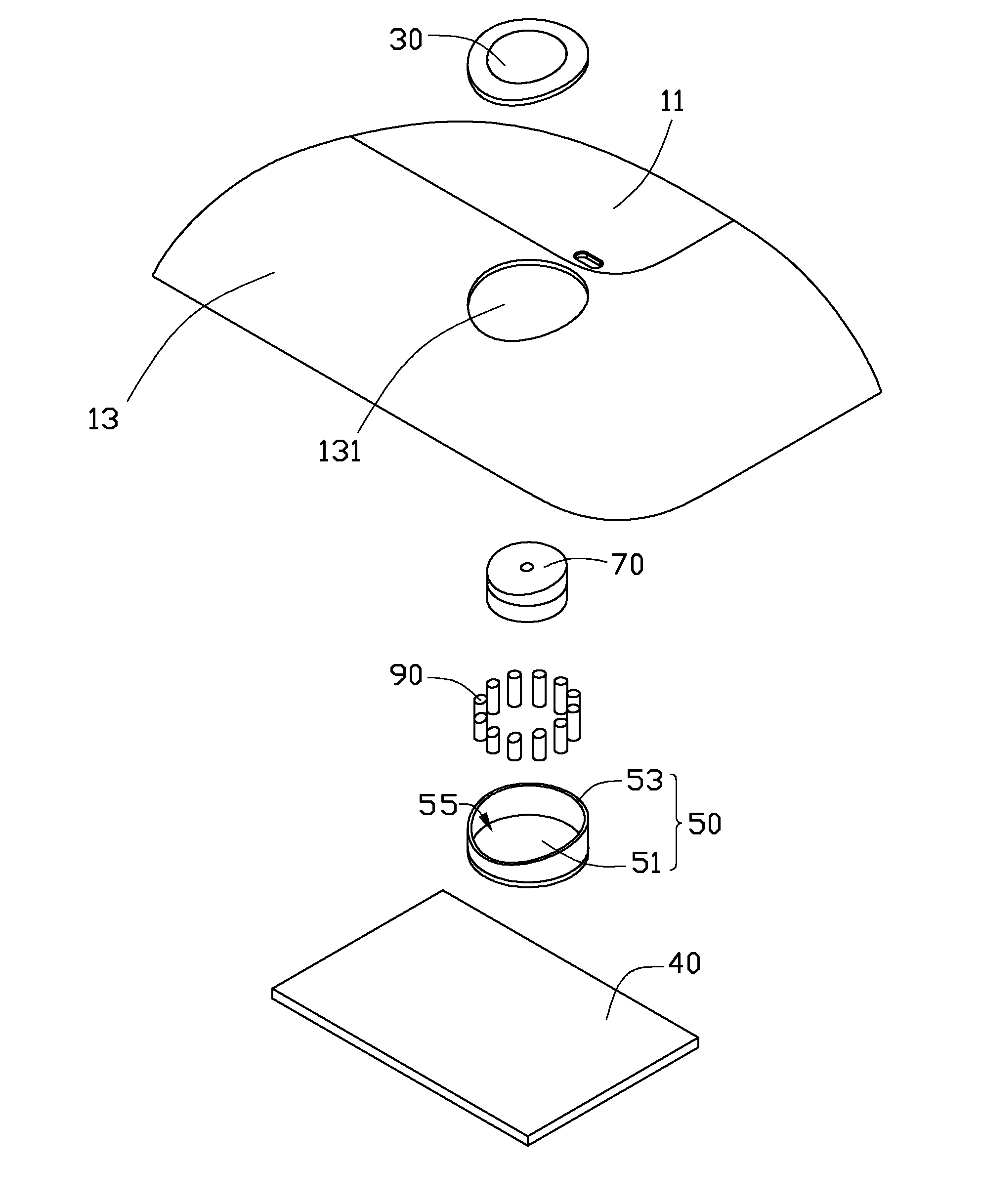
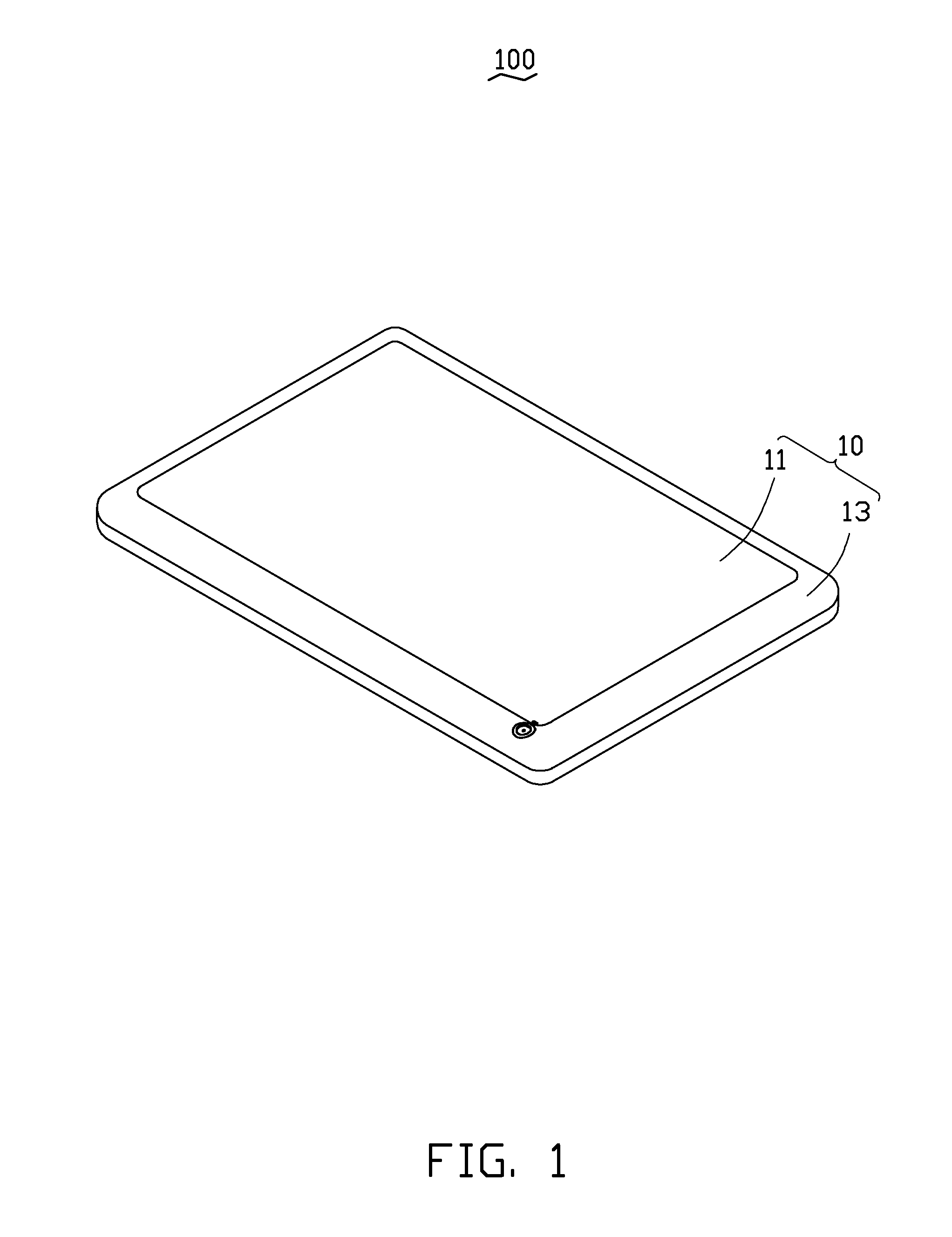
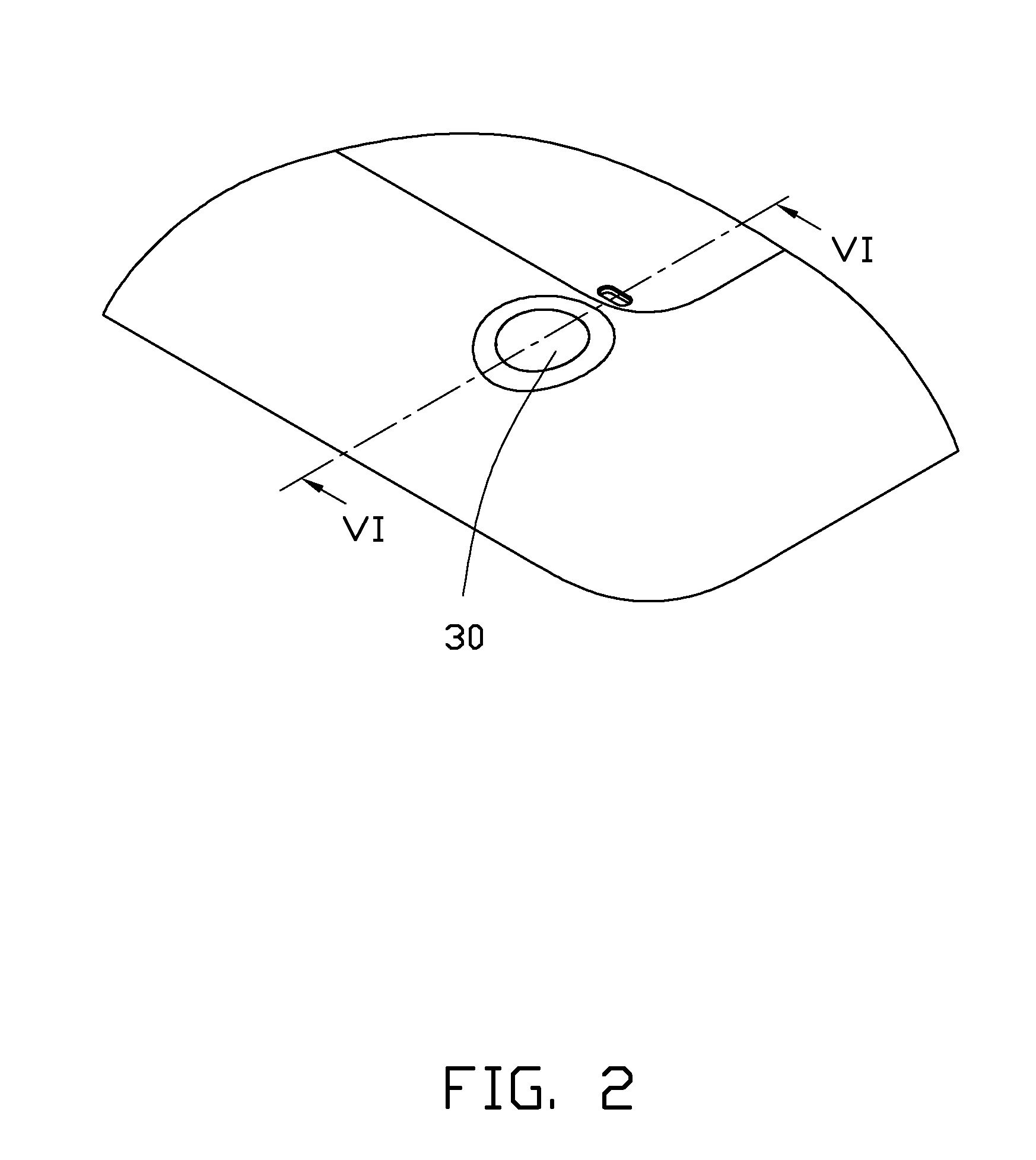
[0013]FIG. 1 is a disclosure of an electronic device 100. In the present embodiment, a tablet computer is illustrated. In other embodiments, the electronic device 100 can be mobile phones, media players or other electronic devices employing a camera module having a lens module. In the embodiment, only the lens module of the camera module is being shown, and the rest of the camera module is omitted herein for brevity. FIG. 1-FIG. 4 show that the electronic device 100 includes a housing 10, a protective cover 30, a mounting board 40, a shield cover 50, a lens module 70, and a plurality of light emitting members 90. The protective cover 30 is mounted on the housing 10 for protecting the lens module 70. The mounting board 40 is positioned in the housing 10 adjacent to the protective cover 30. The shield cover 50 is mounted on the mounting board 40 facing the protective cover 30. The lens module 70 is positioned and received in the shield cover 50. The plurality of the light emitting mem...


PUM


Abstract

An electronic device includes a housing, a shield cover, a camera module, and a plurality of light emitting members. A connecting hole is defined in the housing. The transparent protective cover is positioned in the connecting hole. The shield cover is positioned in the housing facing the connecting hole. The camera module is positioned and is received in the shield cover. The plurality of light emitting members is positioned and is received in the shield cover around the camera module.

Description

BACKGROUND[0001]1. Technical Field[0002]The present disclosure generally relates to electronic devices, and particularly to an electronic device with a camera module.[0003]2. Description of the Related Art[0004]Electronic devices, such as tablet computers, mobile phones, usually include a camera module for taking or capturing photos, video chatting and camera shooting. But imaging quality of the captured photos or videos is not good if the camera module of electronic device works in an environment under weak light. A flash lamp is usually positioned adjacent to the camera module in the electronic device to improve illumination brightness. However, the light from the flash lamp is illuminated immediately and scattered in all directions to negatively affect the image quality, such as producing shining areas that can be found in the captured images.[0005]Therefore, there is room for improvement within the art.BRIEF DESCRIPTION OF THE DRAWING[0006]The components in the drawings are not ...

Claims


Application Information

Patent Timeline
IPC IPC(8): H04N5/225G03B11/04G03B15/05
CPCH04N5/2256H04N23/56H04N23/57
Inventor DUAN, JU-PINGLUO, MING-FU
Owner FU TAI HUA IND SHENZHEN
Why Eureka
Try Eureka