
Method and apparatus for identifying a possible collision object

Active Publication Date: 2014-03-13
BAYERISCHE MOTOREN WERKE AG
View PDF5 Cites 4 Cited by
  • Summary
  • Abstract
  • Description
  • Claims
  • Application Information

AI Technical Summary

Benefits of technology

[0015]In a further advantageous development, the predefined object category comprises predefined types of animals, pedestrians and/or bicyclists who are situated and/or are moving in the edge area of a road and/or on a road, on which the motor vehicle is driving. This makes it advantageously possible that predefined types of animals, pedestrians and/or bicy

Problems solved by technology

When driving at night, a driver's visual range is essentially determined by an illumination of the road by means of front headlights of the vehicle, in which case night vision is frequently temporarily im

Method used


Image

  • Method and apparatus for identifying a possible collision object
  • Method and apparatus for identifying a possible collision object
  • Method and apparatus for identifying a possible collision object

Examples


Example

DETAILED DESCRIPTION OF THE DRAWINGS

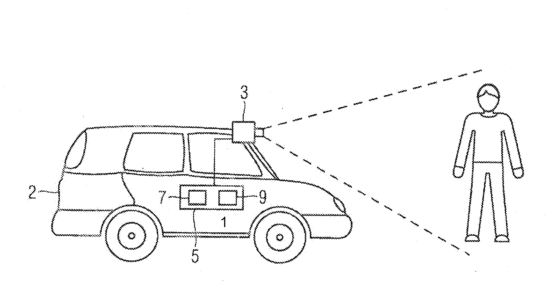
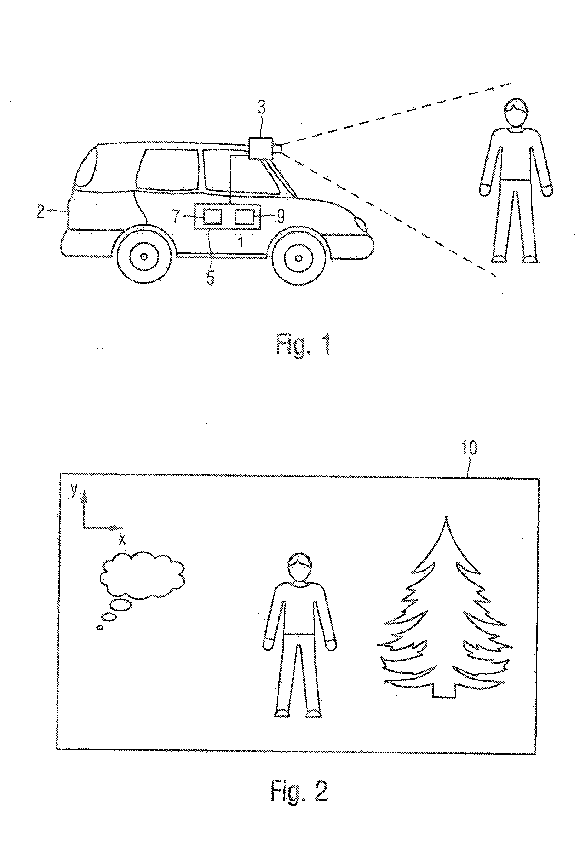
[0024]FIG. 1 is a schematic view of a detection system 1 for a motor vehicle 2. The detection system 1 includes an imaging unit 3 and a control device 5 having an image processing unit 7 and an analyzing unit 9. The control device 5 may also be called a device for detecting a potential collision object. The detection system 1 is, for example, arranged in the motor vehicle 2. The imaging unit 3 may, for example, be arranged in the area of a radiator grille of a motor vehicle and / or in the area of an outside mirror of the vehicle. The detection system 1 preferably includes a night vision system, and the imaging unit 3 is, for example, designed for acquiring a thermal image. The imaging unit 3 may, for example, be an infrared camera.

[0025]The imaging unit 3 is preferably arranged in the motor vehicle 2 in such a fashion that it has an acquisition range pointing in the forward direction of the vehicle. The imaging unit 3 is, for example, designed for ...


PUM


Abstract

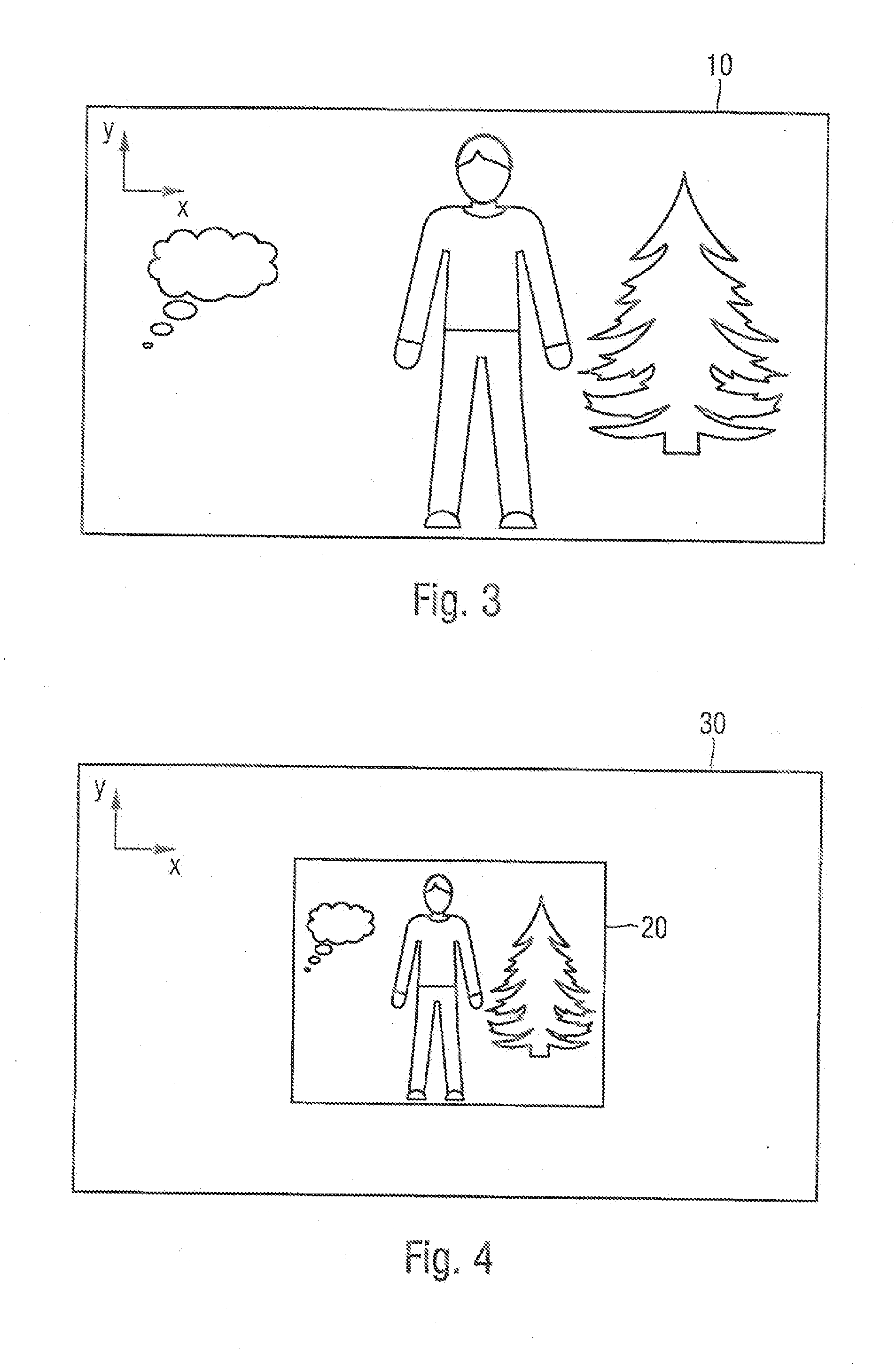
An imaging unit is arranged in a motor vehicle. The imaging unit is designed for providing, as a function of an image acquired by it, a digital source image of a predefined image size. A first intermediate image of a predefined first intermediate image size is generated by reducing a resolution of the source image for the sake of reducing pixels. Furthermore, a second intermediate image of the predefined image size is generated such that it comprises the first intermediate image. The second intermediate image is analyzed by a predefined detector in order to examine whether an object of a predefined object category is situated in the second intermediate image, the detector being designed for analyzing a predefined image detail and for detecting an object of a predefined object category of a predefined object size range.

Description

CROSS REFERENCE TO RELATED APPLICATIONS[0001]This application is a continuation of PCT International Application No. PCT / EP2012 / 058421, filed May 8, 2012, which claims priority under 35 U.S.C. §119 from German Patent Application No. 10 2011 076 112.8, filed May 19, 2011, the entire disclosures of which are herein expressly incorporated by reference.BACKGROUND AND SUMMARY OF THE INVENTION[0002]The invention relates to a method and a device for detecting a potential collision object in an image, which image is acquired by an imaging unit arranged in a motor vehicle, the imaging unit being designed for providing a digital source image of a predefined image size as a function of the acquired image. The invention further relates to a detection system for a motor vehicle.[0003]When driving at night, a driver's visual range is essentially determined by an illumination of the road by means of front headlights of the vehicle, in which case night vision is frequently temporarily impaired by g...

Claims


Application Information

Patent Timeline
IPC IPC(8): G06K9/00
CPCG06K9/00805G08G1/166G06V20/58
Inventor ORECHER, SEBASTIAN
Owner BAYERISCHE MOTOREN WERKE AG
Learn More