
Data collection system for electric discharge machines

a data collection and electric discharge technology, applied in process control, process control, instruments, etc., can solve the problems of small data storage capacity, long machining time in terms of storage capacity, and difficulty in storing multiple kinds of monitoring information over all, and achieve the effect of large volume of monitoring information

Active Publication Date: 2014-03-20
FANUC LTD
View PDF12 Cites 2 Cited by
  • Summary
  • Abstract
  • Description
  • Claims
  • Application Information

AI Technical Summary

Benefits of technology

The present invention is a data collection system for electric discharge machines. It minimizes the amount of monitoring information stored in the machine's storage units and sends only necessary information to a computer when it exceeds a certain level. This reduces network load and prevents data overflow. The system also allows for storing various kinds of monitoring information using different forms and ranges, based on the physical quantity being measured. Additionally, if the physical quantity exceeds a certain level, the system sends it to the computer and stops the machine's operation to prevent damage to the product and avoid waste machining. Overall, this system enables efficient storage and utilization of monitoring information, even without a large-capacity storage device, and reduces the risk of data overflow and production defects.

Problems solved by technology

Such a numerical controller mounted on an electric discharge machine, however, typically has a smaller data storage capacity than a personal computer or a server.
This makes it difficult to store multiple kinds of monitoring information over all routes of electric discharge machining that takes a long machining time in terms of storage capacity.
Also, mounting a large-capacity storage device on an electric discharge machine for storing various kinds of monitoring information increases costs of the electric discharge machine.
While this scheme avoids the problem of increase in costs of the electric discharge machine caused by mounting a large-capacity storage on the electric discharge machine as in the case of the above-mentioned patent document, constant transfer of data over a network can increase communication load on the network or result in monitoring information not being stored in the computer in the event of a failure on the network.
This scheme, however, has the disadvantage of data volume becoming large because it stores monitoring information at predetermined time intervals.

Method used


Image

  • Data collection system for electric discharge machines
  • Data collection system for electric discharge machines
  • Data collection system for electric discharge machines

Examples


Embodiment Construction

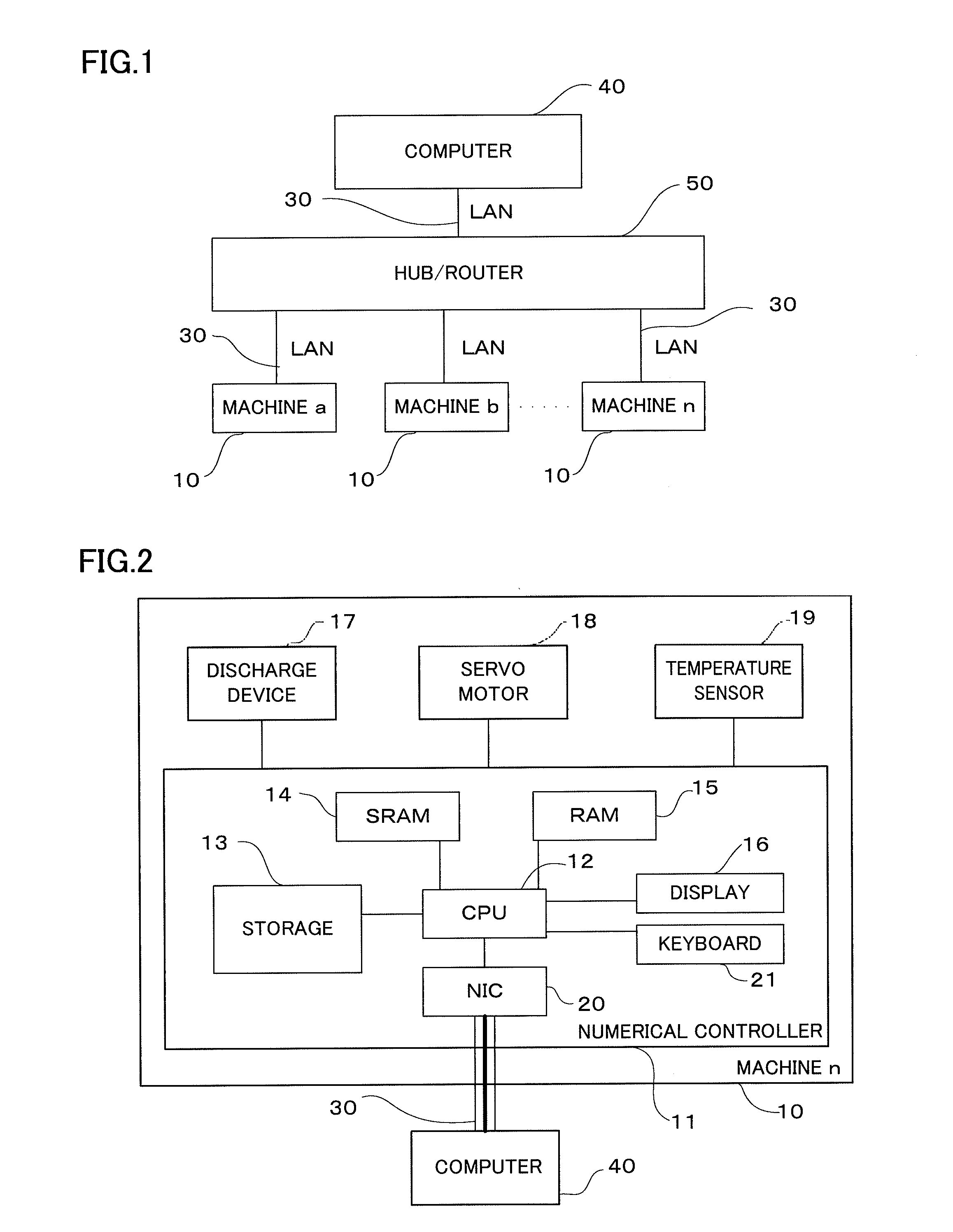
[0032]Referring to FIG. 1, a data collection system for electric discharge machines 10 according to the present invention will be generally described first.

[0033]Multiple electric discharge machines 10 (machines a, b, . . . , n) are connected with a computer 40 via a hub and router 50. Between the computer 40 and the hub / router 50, and between the hub / router 50 and each of machines a, b, . . . , and n are connected by LANs 30. While between the computer 40 and the hub / router 50, and between the hub / router 50 and the individual machines are connected by LANs 30 in the example of FIG. 1, they may be connected by network connection means other than LANs.

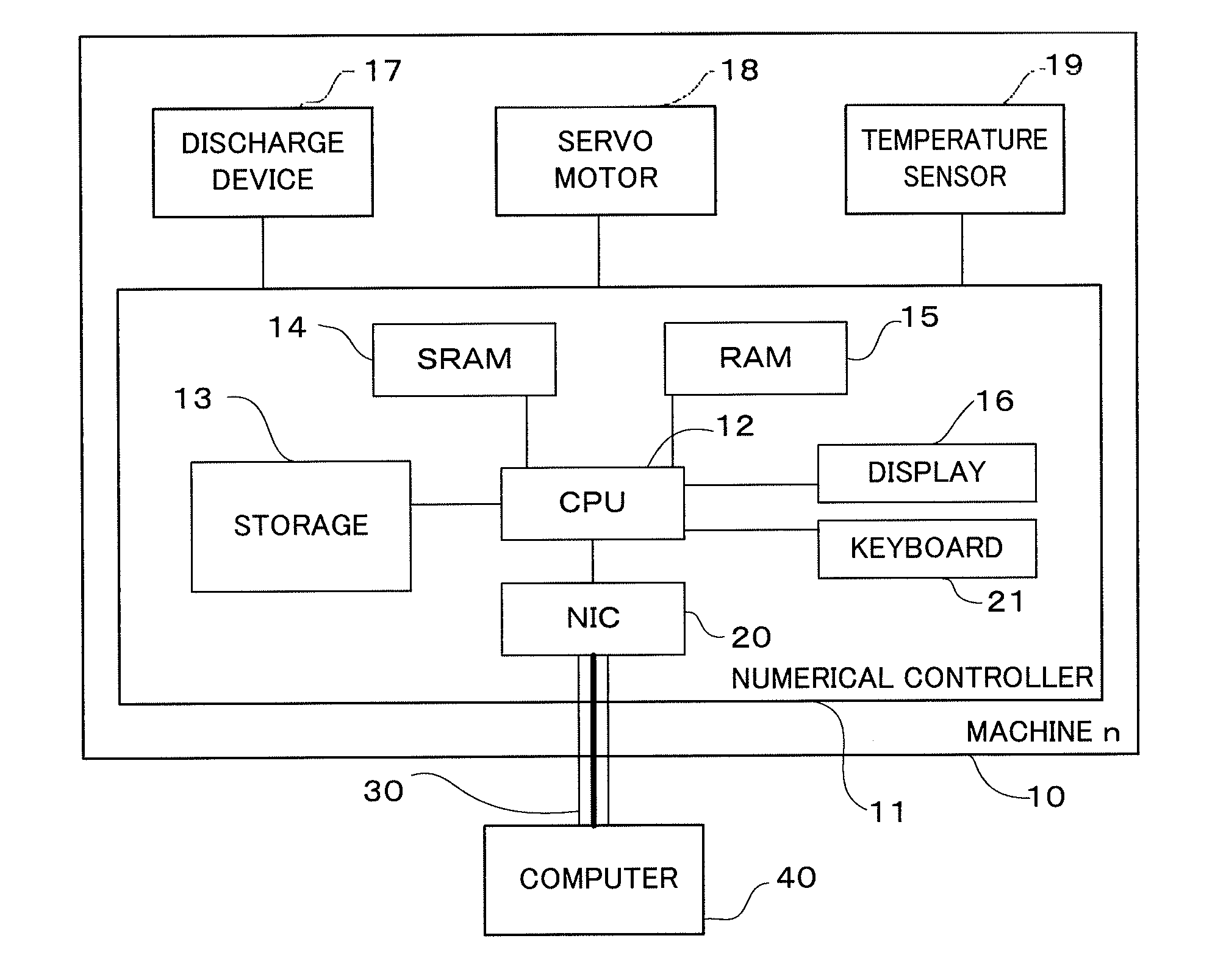
[0034]Turning to FIG. 2, a numerical controller 11 included in each electric discharge machine 10 (machine n) is described.

[0035]As also shown in FIG. 1, the electric discharge machine 10 (machine n) is connected with the computer 40 by a LAN and includes a numerical controller 11, a discharge device 17, a servo motor 18, and a temperat...


PUM

PropertyMeasurementUnit
physical quantityaaaaaaaaaa
distanceaaaaaaaaaa
temperatureaaaaaaaaaa

Abstract

In a data collection system for electric discharge machines, multiple electric discharge machines are connected with a computer over a data transmission path. Information on machining conditions of an electric discharge machine is stored in a storage unit of the electric discharge machine, and information sent from the electric discharge machine after completion of machining is collected by the computer. By minimizing monitoring information that is temporarily stored in the storage unit, various kinds of monitoring information can be stored without being affected by a network environment.

Description

BACKGROUND OF THE INVENTION[0001]1. Field of the Invention[0002]The present invention relates to a data collection system for electric discharge machines in which a computer is connected with electric discharge machines over a network.[0003]2. Description of the Related Art[0004]A known technique for assessing the quality of a machined product manufactured by machining with an electric discharge machine is to measure and assess the surface roughness or dimensional accuracy of the machined product after machining. However, general assessing method of the quality of a machined product is to obtain monitoring information, such as machining voltage, machining current and machining speed which are used for keeping track of machining conditions during machining, and to asses the obtained monitoring information by determining the monitoring information falls within a prescribed range or not. And such obtained monitoring information is stored in a storage device in a numerical controller mo...

Claims


Application Information

Patent Timeline
Patent Type & Authority Applications(United States)
IPC IPC(8): B23H1/02
CPCB23H1/02G05B19/406G05B2219/45221G05B2219/35529G05B2219/37533
Inventor TAKEMOTO, MASANOBU
Owner FANUC LTD
Learn More