Electric power conversion apparatus, power storage system and power storage method
a technology of electric power conversion and power storage system, which is applied in the direction of home appliance efficiency improvement, transportation and packaging, and sustainable buildings, can solve the problems of electric power eg, electric power eg, and the efficiency with which charging can be performed is reduced, so as to reduce the waste of electric power generated, reduce the waste of electric power, and perform the charging with efficiency improvement
- Summary
- Abstract
- Description
- Claims
- Application Information
AI Technical Summary
Benefits of technology
Problems solved by technology
Method used
Image
Examples
first embodiment
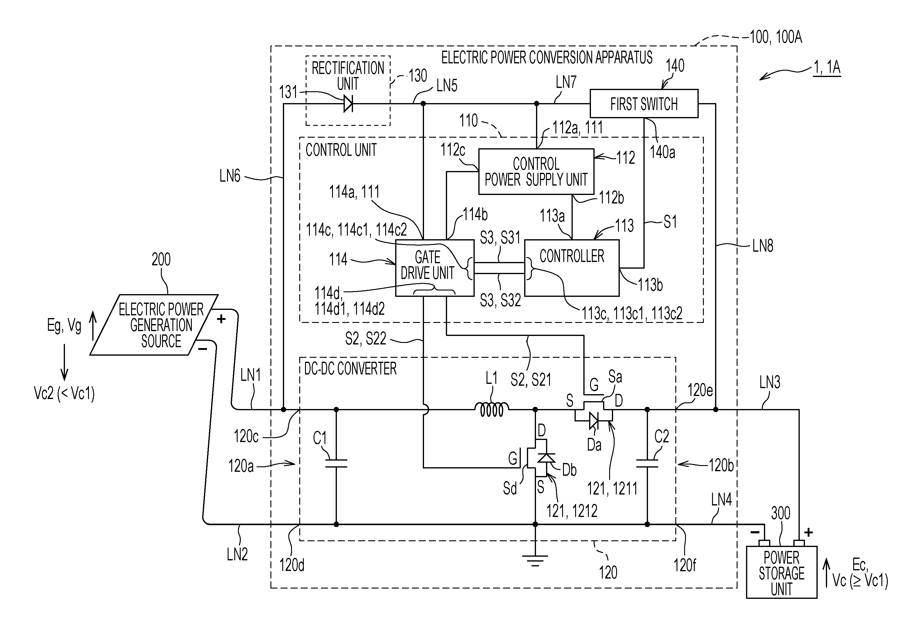
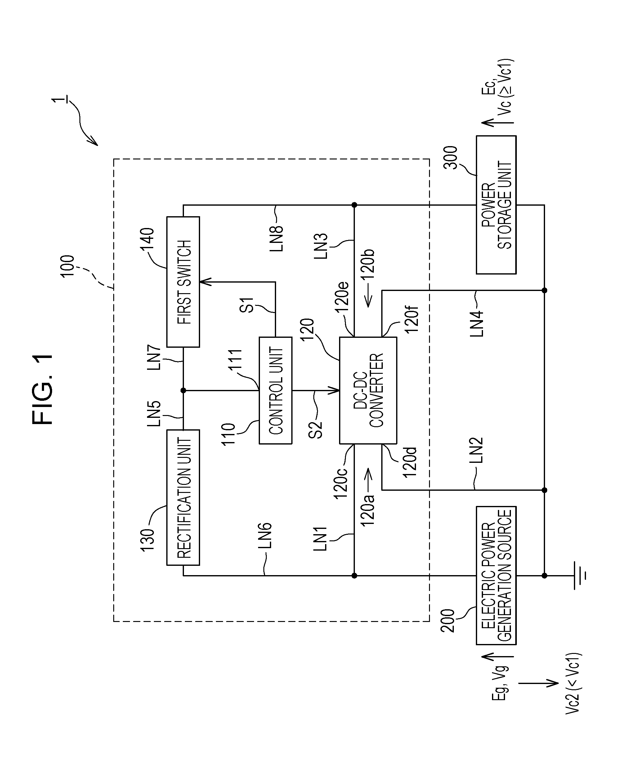
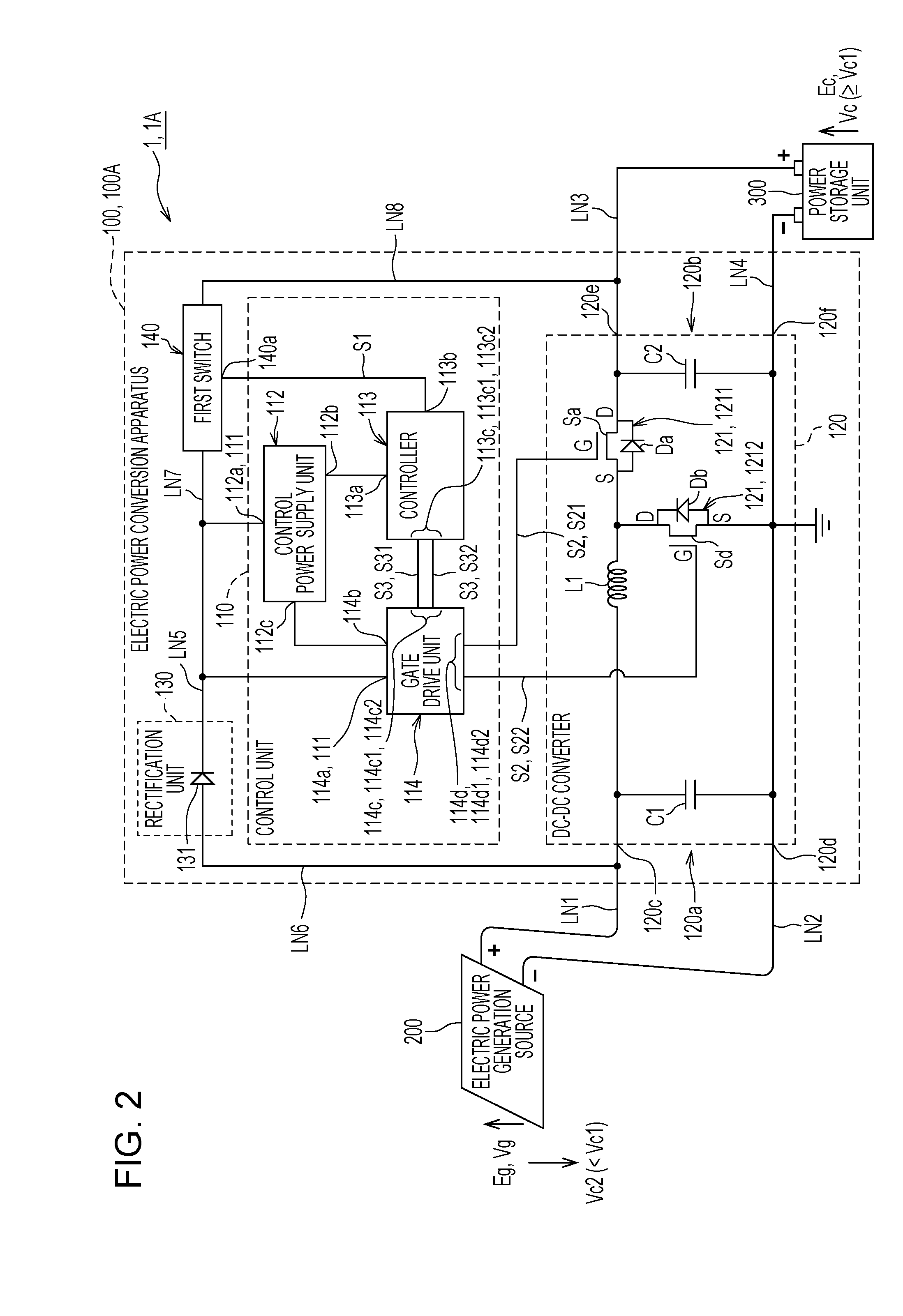
[0047]Next, a detailed circuit configuration of the electric power conversion apparatus 100 according to a first embodiment illustrated in FIG. 1 is described below referring FIG. 2 and FIG. 3.
[0048]Here, the electric power conversion apparatus 100 (100A) according to the first embodiment constitutes a step-up DC-DC converter that steps up an output of the electric power generation source 200 and performs charging on the power storage unit 300 with the stepped-up output of the electric power generation source 200.
[0049]FIG. 2 is a circuit diagram schematically illustrating the detailed circuit configuration of the electric power conversion apparatus 100 (100A) according to the first embodiment.
[0050]The control unit 110, as illustrated in FIG. 2, includes a control power supply unit 112, a controller 113, and a gate drive unit (specifically a gate driver) 114.
[0051]The control power supply unit 112 includes a control power input unit 112a (the electric power input unit 111) to which...
second embodiment
[0098]Next, a detailed circuit configuration of an electric power conversion apparatus 100 according to a second embodiment, illustrated in FIG. 1, is described below referring to FIGS. 5 and 6.
[0099]FIG. 5 is a circuit diagram schematically illustrating the detailed circuit configuration of the electric power conversion apparatus 100 (100B) according to the second embodiment.
[0100]The electric power conversion apparatus 100 (100A) according to the first embodiment, illustrated in FIG. 2, constitutes the step-up DC-DC converter, but the electric power conversion apparatus 100 (100B) according to the second embodiment, illustrated in FIG. 5, constitutes a step-up and step-down DC-DC converter.
[0101]The electric power conversion apparatus 100 (100B) according to the second embodiment, illustrated in FIG. 5, has the same configuration as the electric power conversion apparatus 100 (100A) according to the first embodiment, illustrated in FIG. 2, except that a second switch 132 is provid...
PUM
 Abstract
Description
Claims
Application Information
 - R&D
- Intellectual Property
- Life Sciences
- Materials
- Tech Scout
- Unparalleled Data Quality
- Higher Quality Content
- 60% Fewer Hallucinations
Browse by: Latest US Patents, China's latest patents, Technical Efficacy Thesaurus, Application Domain, Technology Topic, Popular Technical Reports.
© 2025 PatSnap. All rights reserved.Legal|Privacy policy|Modern Slavery Act Transparency Statement|Sitemap|About US| Contact US: help@patsnap.com


