
Image inspection apparatus, image inspection system and image inspection method

a technology of image inspection apparatus and inspection method, which is applied in the direction of image analysis, instruments, computing, etc., can solve the problems of requiring the generation of defect matched to the image scanning capability of the apparatus, and the inefficiency of generating a master image from printed matter as a reference image,

Inactive Publication Date: 2014-03-20
RICOH KK
View PDF7 Cites 39 Cited by
  • Summary
  • Abstract
  • Description
  • Claims
  • Application Information

AI Technical Summary

Benefits of technology

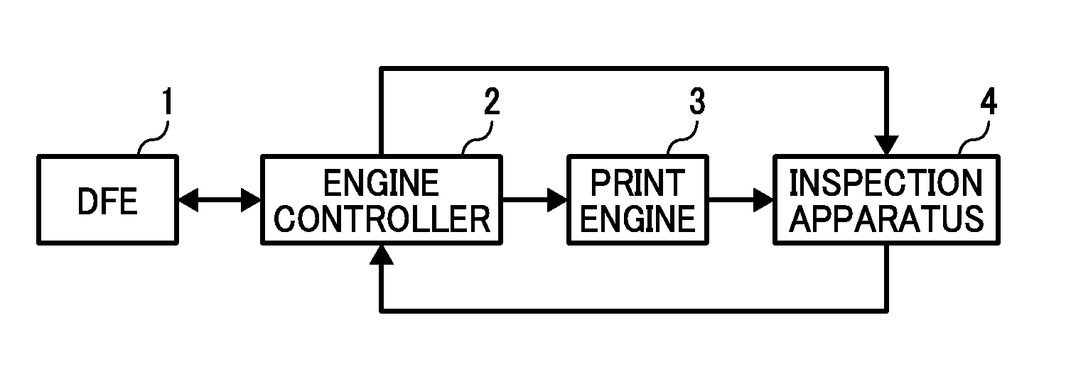
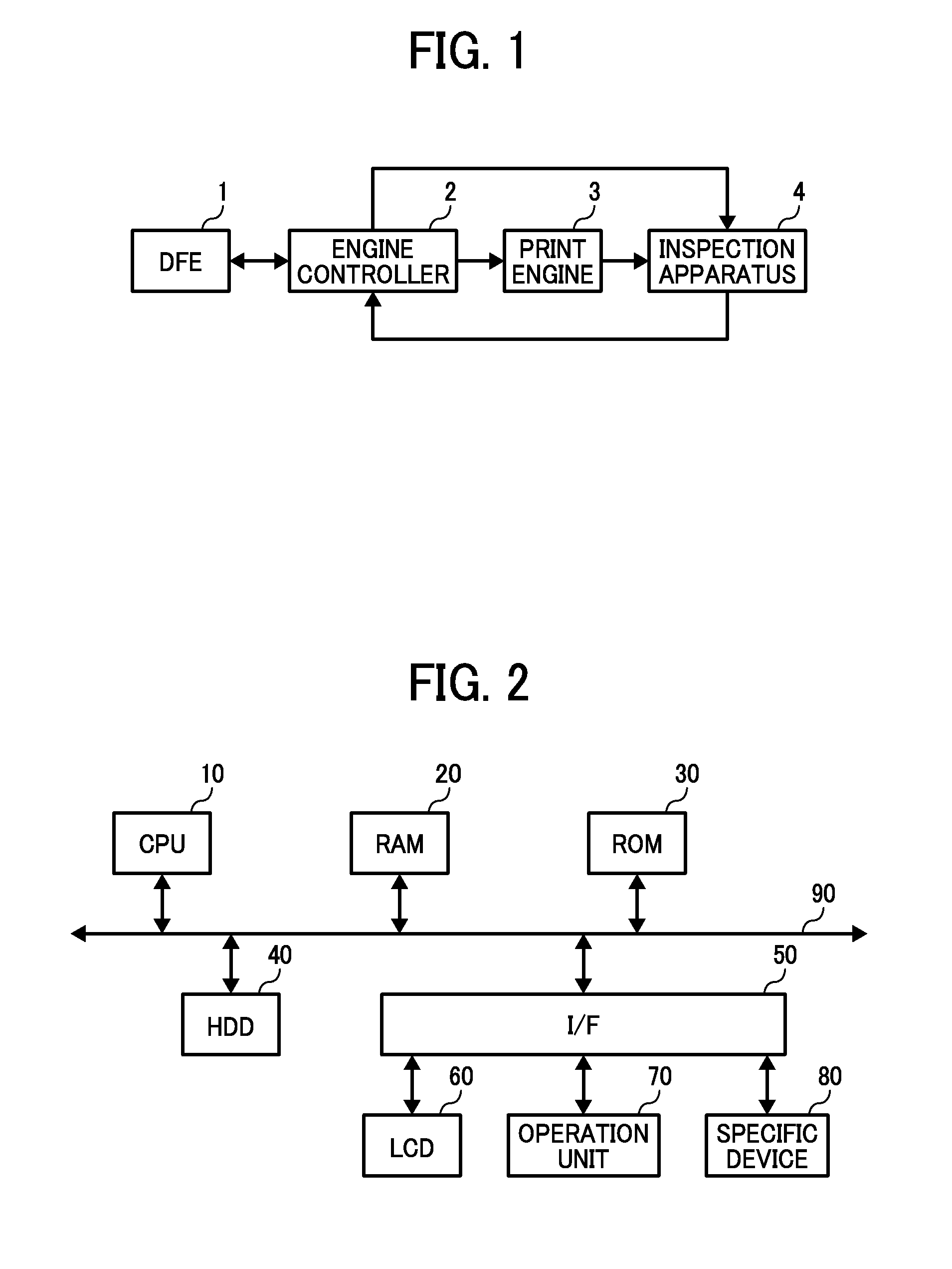
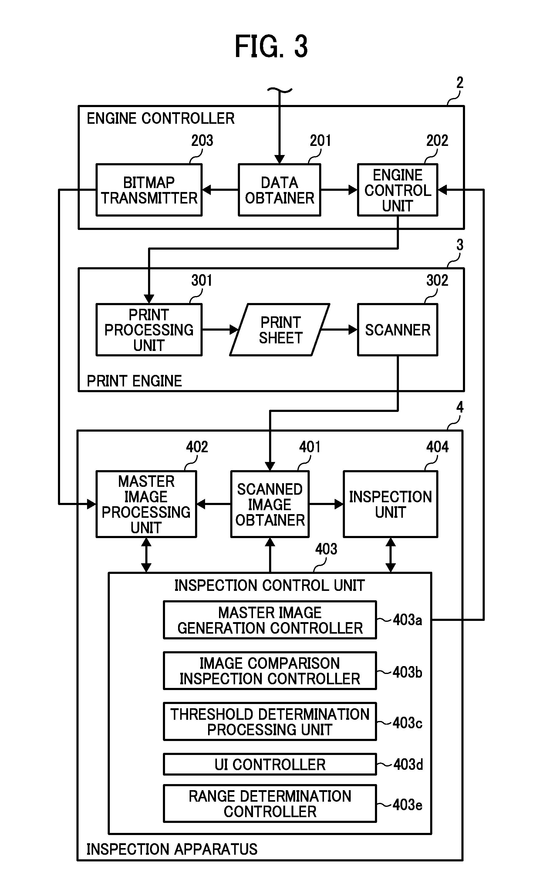
The present invention relates to an image inspection apparatus and system for inspecting images output on a recording medium. The apparatus and system include an inspection reference image generator, an image inspection unit, a threshold determiner, and a defect range determiner. The inspection reference image is generated by adding an artificial defect to an output-target image and used for image inspection. The image inspection unit compares the scanned image with the inspection reference image and determines whether there is a defect based on the difference between the two. The threshold determiner controls the generation of the inspection reference image and computes the difference for each artificial defect. The defect range determiner determines the range of defect levels for the threshold. The technical effects of the invention include improved accuracy and efficiency in inspecting images and reduced human error.

Problems solved by technology

However, the printing apparatuses of digital to press such as image forming apparatuses using electrophotography typically print images with a small volume, and also print different images for each page (i.e. variable printing), in which generating a master image from printed matter as a reference image is not efficient.
However, because image scanning capability of each apparatus is different, when generating the plurality of defects having different levels, the defect matched to the image scanning capability of apparatus is required to be generated and output.

Method used


Image

  • Image inspection apparatus, image inspection system and image inspection method
  • Image inspection apparatus, image inspection system and image inspection method
  • Image inspection apparatus, image inspection system and image inspection method

Examples


Embodiment Construction

[0040]A description is now given of exemplary embodiments of the present invention. It should be noted that although such terms as first, second, etc. may be used herein to describe various elements, components, regions, layers and / or sections, it should be understood that such elements, components, regions, layers and / or sections are not limited therefore because such terms are relative, that is, used only to distinguish one element, component, region, layer or section from another region, layer or section. Thus, for example, a first element, component, region, layer or section discussed below could be termed a second element, component, region, layer or section without departing from the teachings of the present invention.

[0041]In addition, it should be noted that the terminology used herein is for the purpose of describing particular embodiments only and is not intended to be limiting of the present invention. Thus, for example, as used herein, the singular forms “a”, “an” and “t...


PUM


Abstract

An image inspection apparatus for inspecting a scanned image of an output image includes an inspection reference image generator to generate an inspection reference image; an image inspection unit to determine a defect by comparing a difference between the inspection reference image and the scanned image with a threshold; a threshold determiner to determine the threshold; and a defect range determiner to determine a range of defect level of a plurality of artificial defects. Based on a difference computed for a defect selected from the plurality of artificial defects, the threshold determiner determines a threshold to be compared with the difference of the selected defect. The defect range determiner conducts a defect determination for the scanned image at the upper and lower limits for a threshold to determine a range of defect level of the plurality of artificial defects.

Description

[0001]This application claims priority pursuant to 35 U.S.C. §119 to Japanese Patent Applications Nos. 2012-203590, filed on Sep. 14, 2012 and 2013-165590, filed on Aug. 8, 2013 in the Japan Patent Office, the disclosure of which is incorporated by reference herein in their entirety.BACKGROUND[0002]1. Technical Field[0003]The present invention relates to an image inspection system and an image inspection method, and more particularly to setting of inspection thresholds used for determining defects in image.[0004]2. Background Art[0005]Conventional inspections of printed matter such as printed papers are conducted by visual inspection, but inspection apparatuses have been introduced to conduct the inspections as a post-processing operation of the offset printing. As for the inspection apparatus, the printed matters are visually inspected by an operator to select a printed matter having satisfactory image quality, and then the selected printed matter is scanned to generate a master im...

Claims


Application Information

Patent Timeline
Patent Type & Authority Applications(United States)
IPC IPC(8): G06T7/00
CPCG06T7/0002H04N1/00005H04N1/00031H04N1/00045H04N1/00058H04N1/00068
Inventor KANEKO, HITOMIKITAI, TADASHI
Owner RICOH KK
Learn More