Image inspection method and image inspection apparatus employing the same

a technology of image inspection and inspection method, which is applied in the direction of image enhancement, photo-taking process, instruments, etc., can solve the problem of very scant practicability

Inactive Publication Date: 2007-11-22
MITSUBISHI ELECTRIC CORP
View PDF11 Cites 28 Cited by
  • Summary
  • Abstract
  • Description
  • Claims
  • Application Information

AI Technical Summary

Benefits of technology

[0010] Since the image inspection method according to this invention is configured as stated above, it can stably and precisely inspect the defects of the object to-be-inspected, such as microscopic flaws, foreign matter, and cracks.
[0011] Besides, since the image inspection apparatus according to this invention is configured as stated above, it can stably and precisely inspect the defects of the object to-be-inspected, such as microscopic flaws, foreign matter, and cracks.

Problems solved by technology

Although automatic inspection is declared to be possible, means therefor is not stated, and the practicability thereof is very scanty.

Method used


Image

  • Image inspection method and image inspection apparatus employing the same
  • Image inspection method and image inspection apparatus employing the same
  • Image inspection method and image inspection apparatus employing the same

Examples


embodiment 1

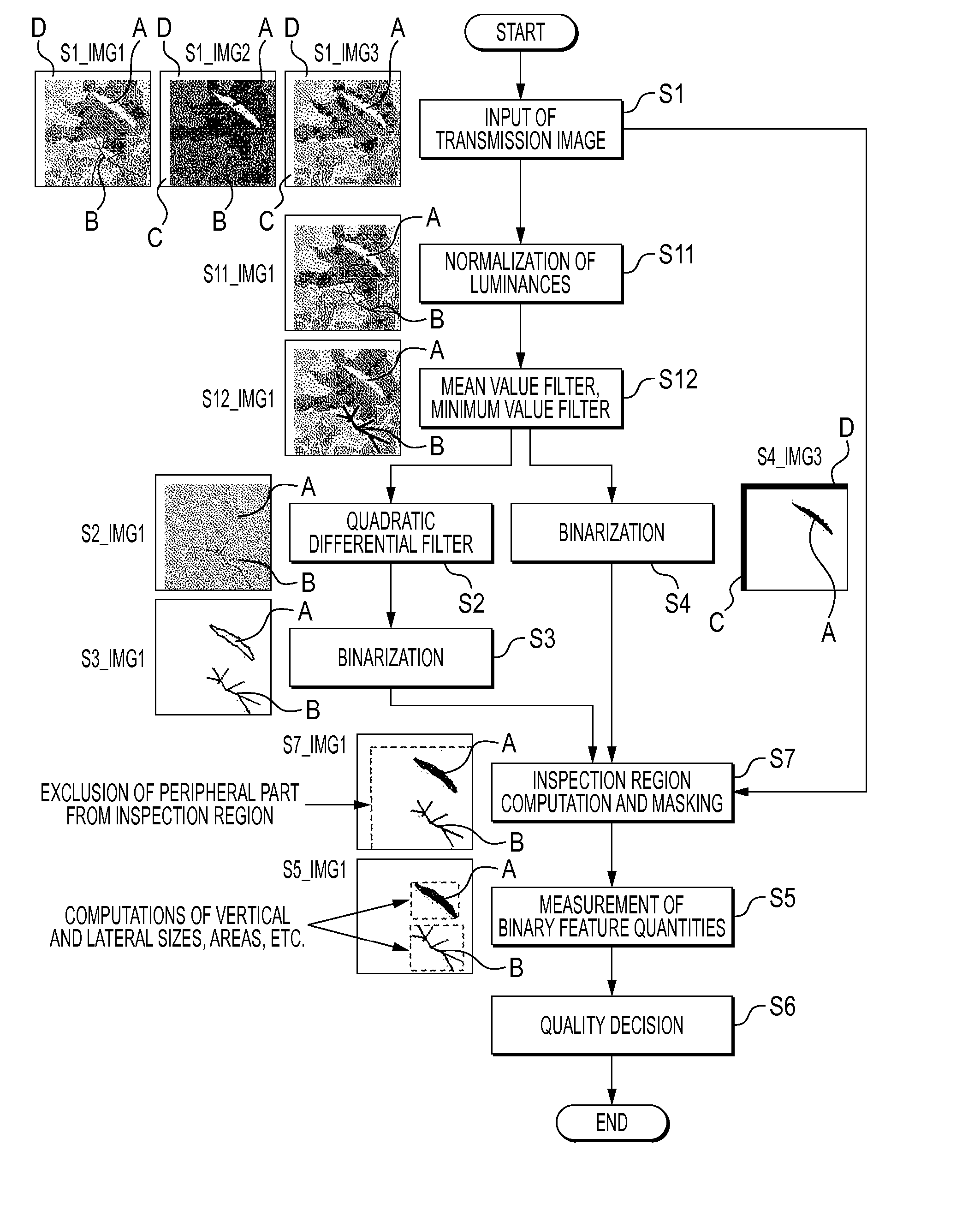
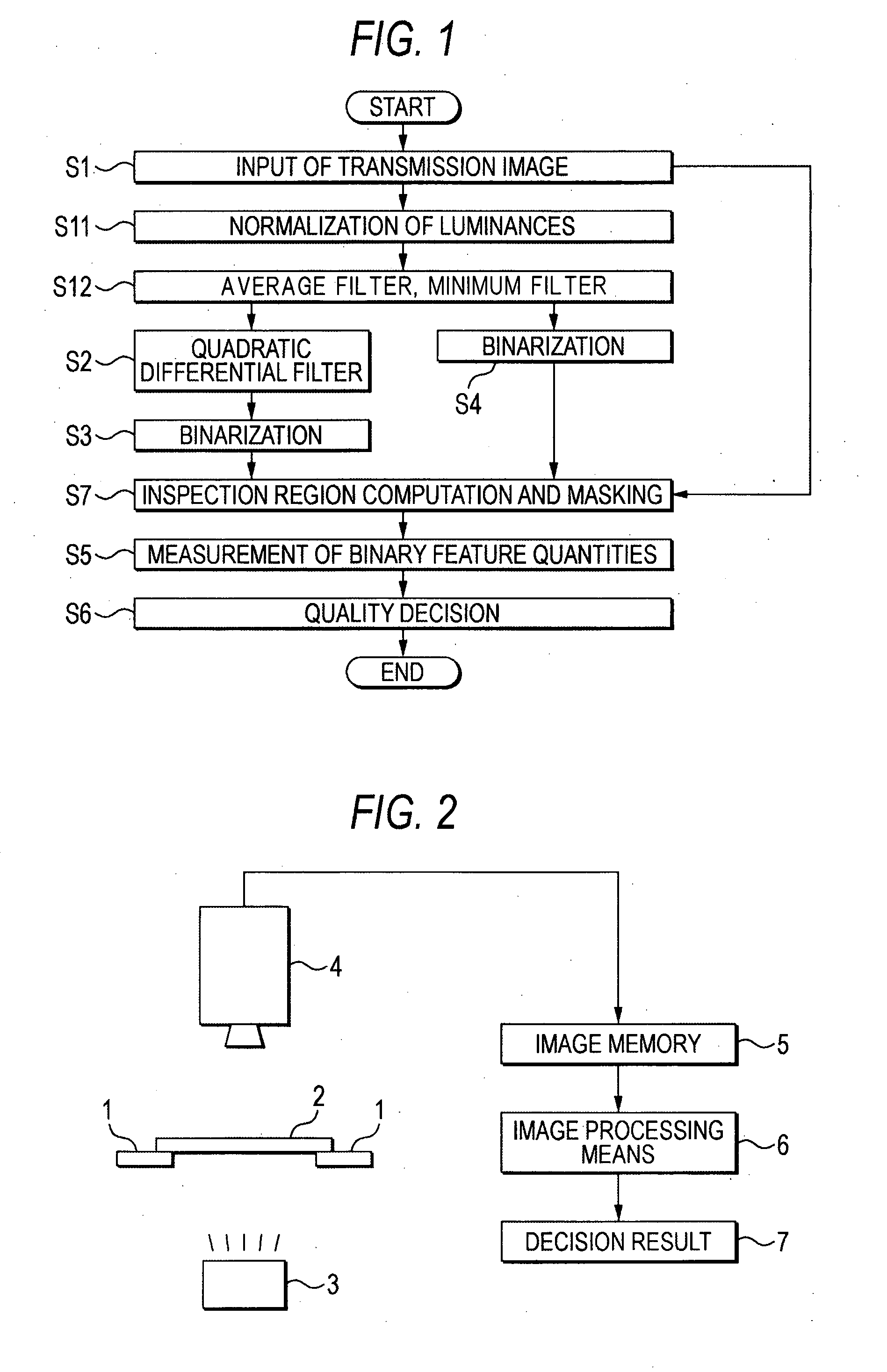
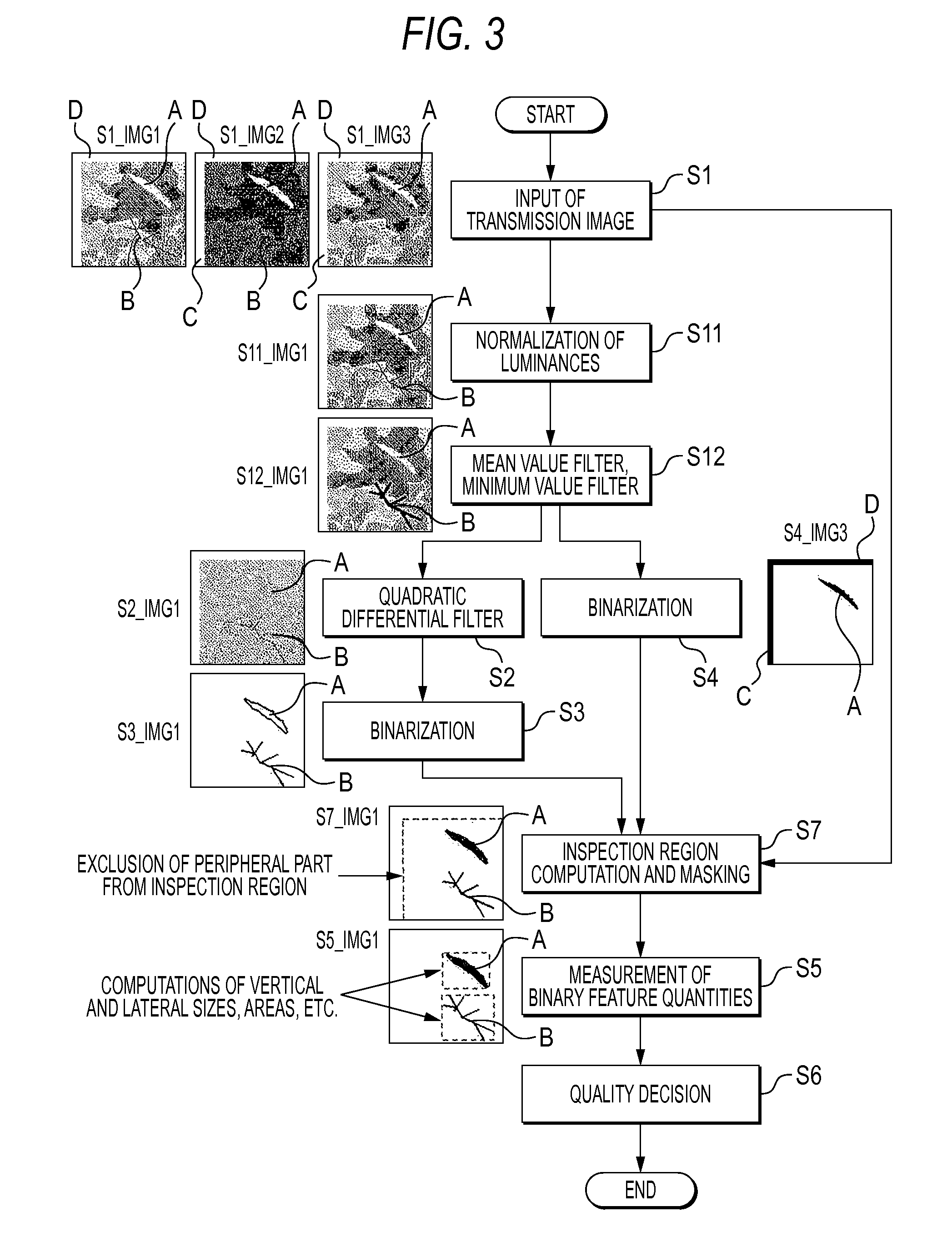
[0016] Now, Embodiment 1 of this invention will be described in conjunction with the drawings. FIG. 1 is a flow chart showing an image inspection method according to Embodiment 1, FIG. 2 is a schematic block diagram showing the configuration of an image inspection apparatus which employs the image inspection method shown in FIG. 1, and FIG. 3 is a flow chart in which intermediate images in the course of the execution of an inspection are added to FIG. 1.

[0017] First, the image inspection apparatus shown in FIG. 2 will be described. The image inspection apparatus includes transmission illumination means 3 for illuminating an object to-be-inspected 2 held on a holder 1, from below, and imaging means 4 disposed over the object to-be-inspected 2, and for imaging an image which is generated in such a way that illumination light emitted from the transmission illumination means 3 is transmitted through the object to-be-inspected 2.

[0018] The image imaged by the imaging means 4 is stored ...

embodiment 2

[0049] Next, Embodiment 2 of this invention will be described. In Embodiment 1, a general filter has been employed as the quadratic differential filter at the step S2, the quadratic differential has been computed by the difference of the luminances of the image, and the X- or Y-distance of the difference has been one picture element. In Embodiment 2, however, the difference distance is not limited to one picture element, but it is expanded to any desired value. In the case, for example, where the oblique direction of 45 degrees is considered in addition to the X- and Y-directions, the following is given:

f″(x, y)=[f(x+h, y+h)+f(x+h, y)+f(x+h, y−h)+f(x, y+h)+f(x, y−h)+f(x−h, y+h)+f(x−h, y)+f(x−h, y−h)−8f(x, y)] / (h×h)  (Formula 5)

Here, “h” denotes the difference distance, and it takes integral values such as h=1, 2 and 3.

[0050] In this invention, generalization is further promoted, and the difference distance h is expanded as a real number as follows: That is, the difference distan...

embodiment 3

[0053] Next, Embodiment 3 of this invention will be described. In Embodiment 1, it has been stated that, in the case where the fluctuations of the thicknesses of the objects to-be-inspected 2 are large, the luminances of the images need to be normalized at the step S11, so as to convert the dark image or the bright image into the image S1_IMG1 of appropriate brightness. However, when the changes of the luminances of the images are excessively large, depending upon the thicknesses of the objects to-be-inspected 2, as in the images S1_IMG1 to S1_IMG3, stable inspection results cannot be expected even by executing the detection processing at the subsequent steps.

[0054] Embodiment 3 indicates a coping method in such a case, and it consists in that the luminances of the images are normalized by adding the step S11, thereby to convert the excessively bright image or the excessively dark image into the image of appropriate brightness. A practicable procedure is as stated below.

[0055] Ass...


PUM


Abstract

The method comprises a first step (S1 in FIG. 1) of obtaining a transmission image, a second step (S2) of applying a quadratic differential filter to the transmission image, thereby to emphasize a part of large luminance change as a quadratic differential filter image, a third step (S3) of binarizing the quadratic differential filter image with a predetermined threshold value, and then storing the resulting binarized image, a fourth step (S4) of binarizing the transmission image with another predetermined threshold value, and then storing the resulting binarized image, a fifth step (S5) of performing the measurement of binary feature quantities for the binarized image stored at the third step (S3) and the binarized image stored at the fourth step (S4), and a sixth step (S6) of deciding the quality of the object to-be-inspected from the binary feature quantities.

Description

BACKGROUND OF THE INVENTION [0001] 1. Field of the Invention [0002] This invention relates to an image inspection method which inspects drawbacks such as flaws, the mixing of foreign matter, and cracks in, for example, a wafer or substrate of semiconductor, and an image inspection apparatus which employs the method. [0003] 2. Description of the Related Art [0004] An image inspection method in the prior art has been such that illumination light is transmitted through or reflected from an object to-be-inspected by employing illumination with infrared radiation or the like, and that the object to-be-inspected is visually inspected on the basis of a resulting transmission image or reflection image. [0005] An example wherein the object is inspected by transmitting the illumination light therethrough is disclosed in Non-patent Document 1, that is, Optical μ-Crack detection in combination with stability testing for in-line-inspection of wafers and cells, 20th European Photovoltaic Solar En...

Claims


Application Information

Patent Timeline
Patent Type & Authority Applications(United States)
IPC IPC(8): G06K9/00
CPCG06T2207/30148G06T7/0004
Inventor NISHINO, HIROHISAUNO, MASAHIKO
Owner MITSUBISHI ELECTRIC CORP
Why Eureka
Try Eureka