
Apparatus, system, and method of inspecting image, and recording medium storing image inspection control program

Active Publication Date: 2013-09-26
RICOH KK
View PDF3 Cites 28 Cited by
  • Summary
  • Abstract
  • Description
  • Claims
  • Application Information

AI Technical Summary

Benefits of technology

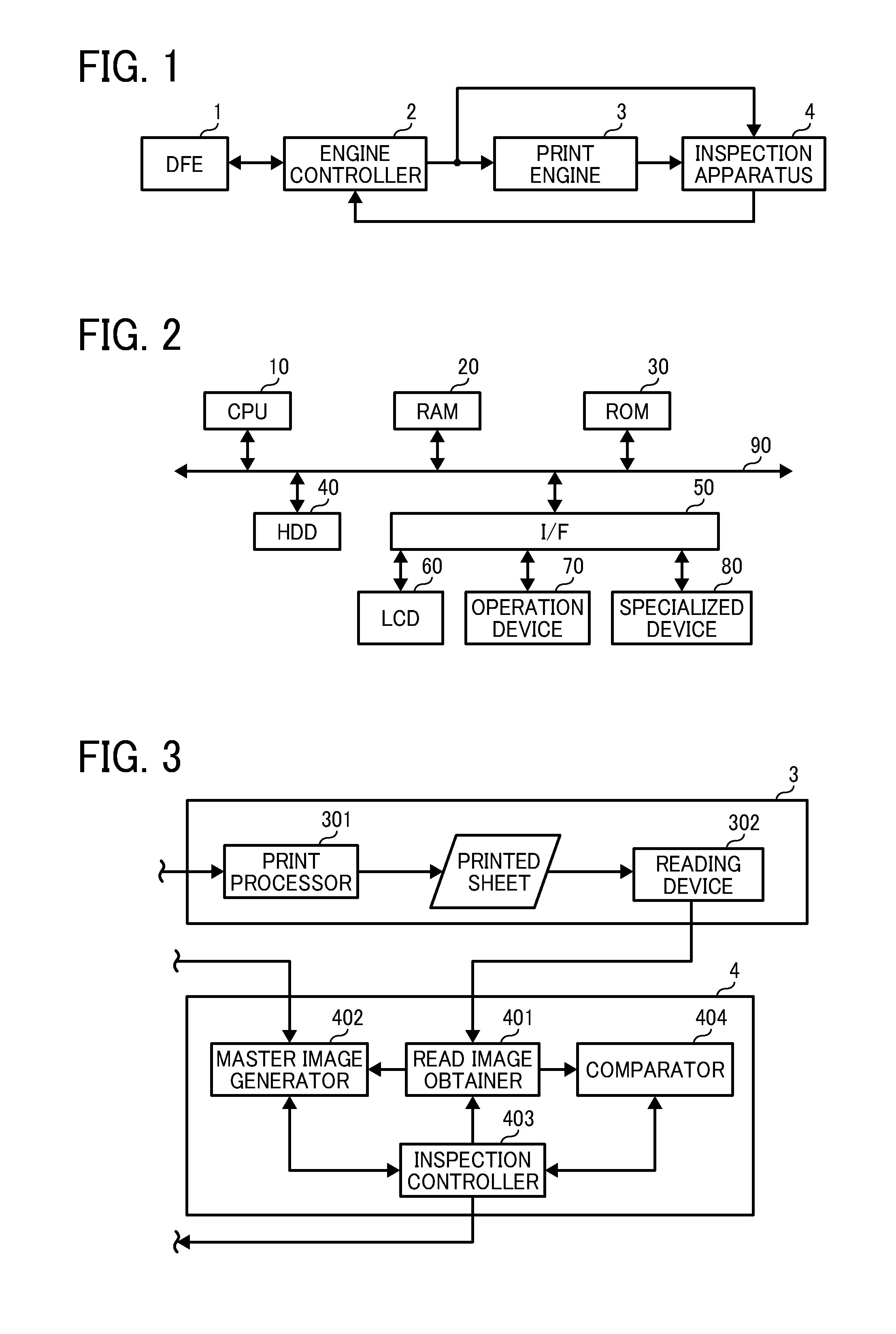
The present invention provides an apparatus, system, method, and non-transitory recording medium storing an image inspection control program capable of inspecting a printed image based on comparison between a read image obtained by reading the printed image and an inspection image. This technology improves accuracy and simplifies the configuration. It enables accurate matching of the read image and inspection image positions, even when the output target image is formed on a recording sheet having a previously printed image. This technology is useful in various printing processes, such as offset printing, inkjet printing, and laser printing.

Problems solved by technology

In such case, comparing the printed matter, with the master image generated from the printed matter, would be inefficient.
This registration shift, even the shift in a few pixels that is not recognizable by the human eye, may have negative influences in image inspection.
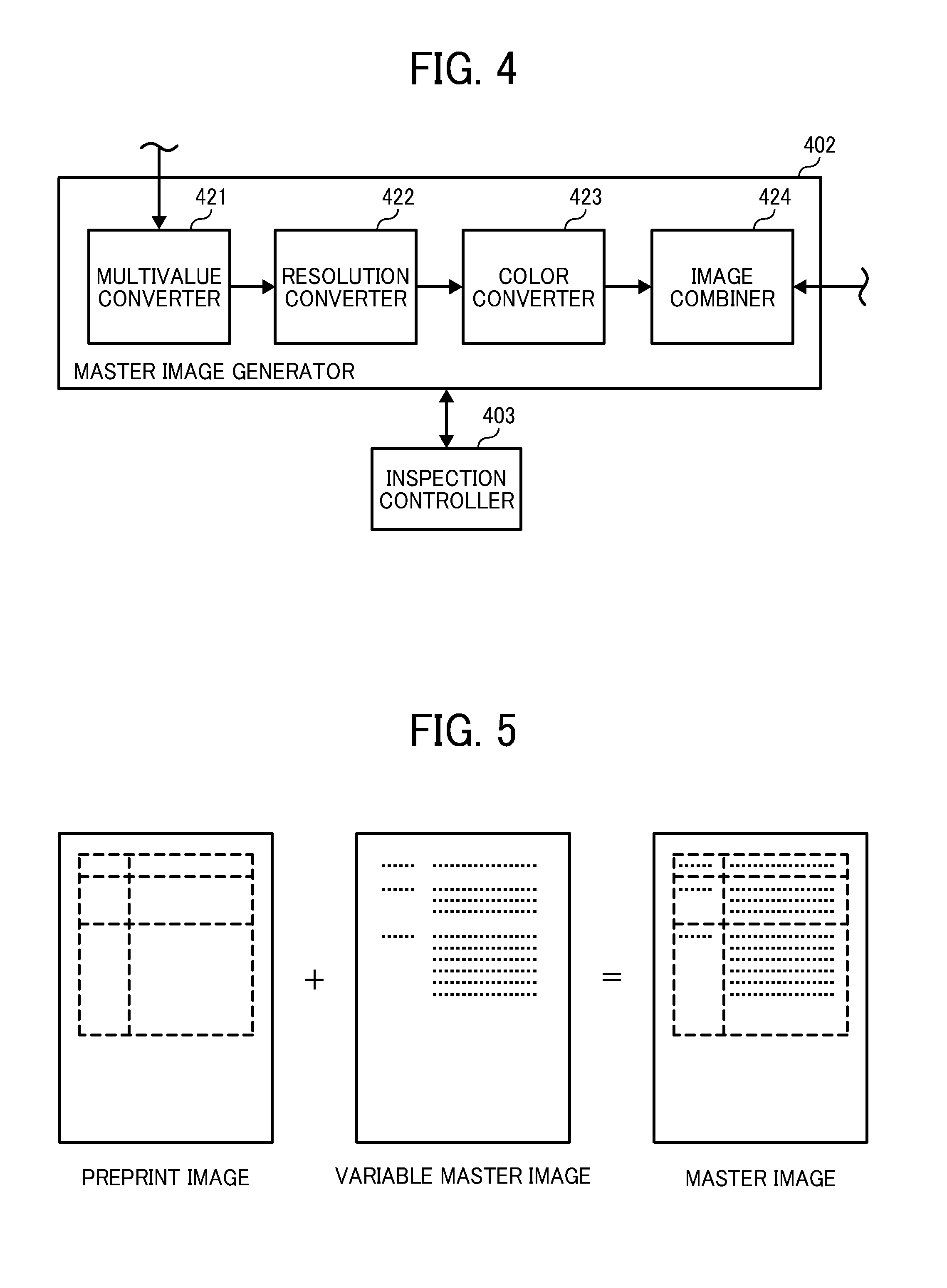
In such case, the master image and the read image would have different images such that it would be difficult to match the positions of the images.
Further, even if a defect is detected in the image, it would be difficult to automatically detect whether the defect is in the preprint image or the variable image, thus making difficult to notify the user of detection of the defect.
If any portion in the preprint image layer is not masked, that portion may be detected as a defect in the read image.
Further, in case the preprint image layer and the variable image layer are closely located in their positions, a portion in the variable image layer may be masked, thus causing an error in detection of a defect.
While the technique described in Japanese Patent Application Publication No. 2005-41122-A also has a drawback as described above, it additionally requires the longer processing time and the higher manufacturing cost.

Method used


Image

  • Apparatus, system, and method of inspecting image, and recording medium storing image inspection control program
  • Apparatus, system, and method of inspecting image, and recording medium storing image inspection control program
  • Apparatus, system, and method of inspecting image, and recording medium storing image inspection control program

Examples


Embodiment Construction

[0036]The terminology used herein is for the purpose of describing particular embodiments only and is not intended to be limiting of the present invention. As used herein, the singular forms “a”, “an” and “the” are intended to include the plural forms as well, unless the context clearly indicates otherwise. It will be further understood that the terms “includes” and / or “including”, when used in this specification, specify the presence of stated features, integers, steps, operations, elements, and / or components, but do not preclude the presence or addition of one or more other features, integers, steps, operations, elements, components, and / or groups thereof.

[0037]In describing example embodiments shown in the drawings, specific terminology is employed for the sake of clarity. However, the present disclosure is not intended to be limited to the specific terminology so selected and it is to be understood that each specific element includes all technical equivalents that operate in a s...


PUM


Abstract

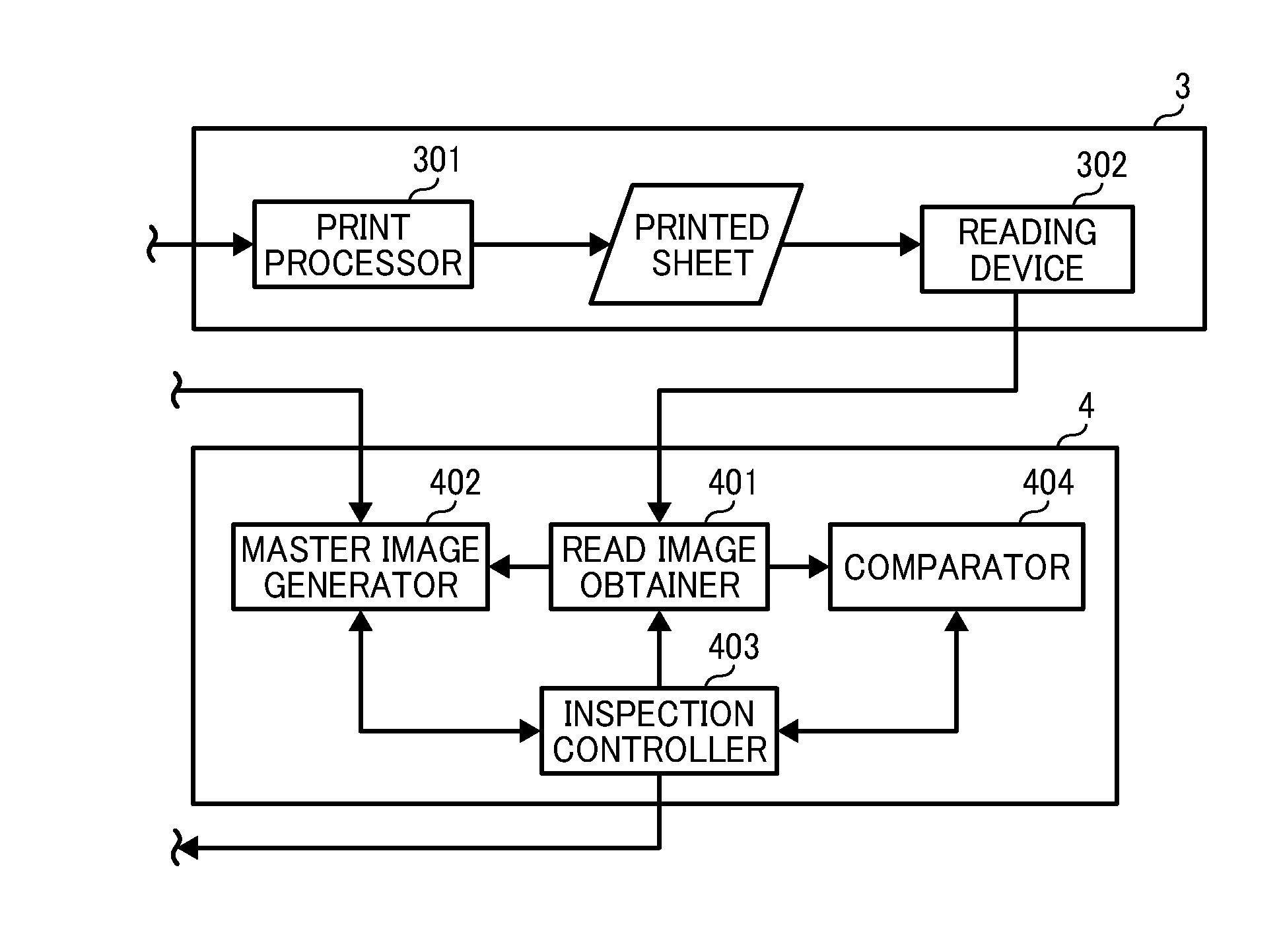
An apparatus, system, method, and non-transitory recording medium storing an image inspection control program, each of which is capable of inspecting a printed image are provided. While generating an inspection image to be used for inspecting a read image obtained by reading the printed image, attribute data indicating, for each pixel in the inspection image, whether the pixel belongs to drawing data in the inspection image is generated. The attribute data is used to process inspection of the read image based on comparison between the read image and the inspection image.

Description

CROSS-REFERENCE TO RELATED APPLICATIONS[0001]This patent application is based on and claims priority pursuant to 35 U.S.C. §119 to Japanese Patent Application No. 2012-063765, filed on Mar. 21, 2012, in the Japan Patent Office, the entire disclosure of which is hereby incorporated by reference herein.BACKGROUND[0002]1. Field of the Invention[0003]The present invention relates to an apparatus, system, and method of inspecting an image and a non-transitory recording medium storing an image inspection control program, and more specifically, to inspecting an image formed on a recording sheet using attribute data.[0004]2. Description of the Related Art[0005]Conventionally, inspection of printed matter is performed by human operators. In recent years, an inspection apparatus that automatically inspects printed matter is widely used, mainly in the field of offset printing. For example, a master image is generated by reading specific printed matter that is selected based on the image qualit...

Claims


Application Information

Patent Timeline
IPC IPC(8): H04N1/00
CPCH04N1/00005H04N1/00047G06K9/033H04N1/40H04N1/00087G06V10/987
Inventor KOJIMA, KEIJIISHIZAKI, HIROYOSHIKITAI, TADASHIKANEKO, HITOMIKAWAMOTO, HIROYUKIMIYAMOTO, KEIICHI
Owner RICOH KK
Learn More