Systems and Methods for Inspecting and Monitoring a Pipeline

a pipeline inspection and pipeline technology, applied in the field of optical analysis systems, can solve the problems of inability to provide adequate reasons as to why the particular defect is occurring or has occurred, inability to efficiently monitor the formation of both organic and inorganic deposits, and inability to achieve real-time or near-real-time analysis capabilities

Active Publication Date: 2014-03-20
HALLIBURTON ENERGY SERVICES INC
View PDF2 Cites 22 Cited by
  • Summary
  • Abstract
  • Description
  • Claims
  • Application Information

AI Technical Summary

Benefits of technology

[0007]In one aspect of the disclosure, a system for monitoring a pipeline is disclosed. The system may include a movable inline inspection device arranged within the pipeline and having a housing that defines a conduit therein, the conduit providing fluid communication through the movable inline inspection device, one or more optical computing devices arranged on the conduit for monitoring a bypass fluid flowing through the conduit, the one or more optical computing devices comprising, at least one integrated computational element configured to optically interact with the bypass fluid and thereby generate optically interacted light, and at least one detector arranged to receive the optically interacted light and generate an output signal corresponding to a characteristic of the bypass fluid. The system may also include a signal processor communicably coupled to the at least one detector of each optical computing device for receiving the output signal of each optical computing device, the signal processor being configured to determine the characteristic of the fluid as detected by each optical computing device a

Problems solved by technology

While conventional smart pigs are generally able to locate various pipeline defects, they are, for the most part, unable to provide adequate reasons as to why the particular defect is occurring or has occurred.
Also, conventional smart pigs are largely unable to efficiently monitor the formation of both organic and inorganic deposits detected in pipelines and flow lines.
Although off-line, retrospective analyses can be satisfa

Method used


Image

  • Systems and Methods for Inspecting and Monitoring a Pipeline
  • Systems and Methods for Inspecting and Monitoring a Pipeline
  • Systems and Methods for Inspecting and Monitoring a Pipeline

Examples


Embodiment Construction

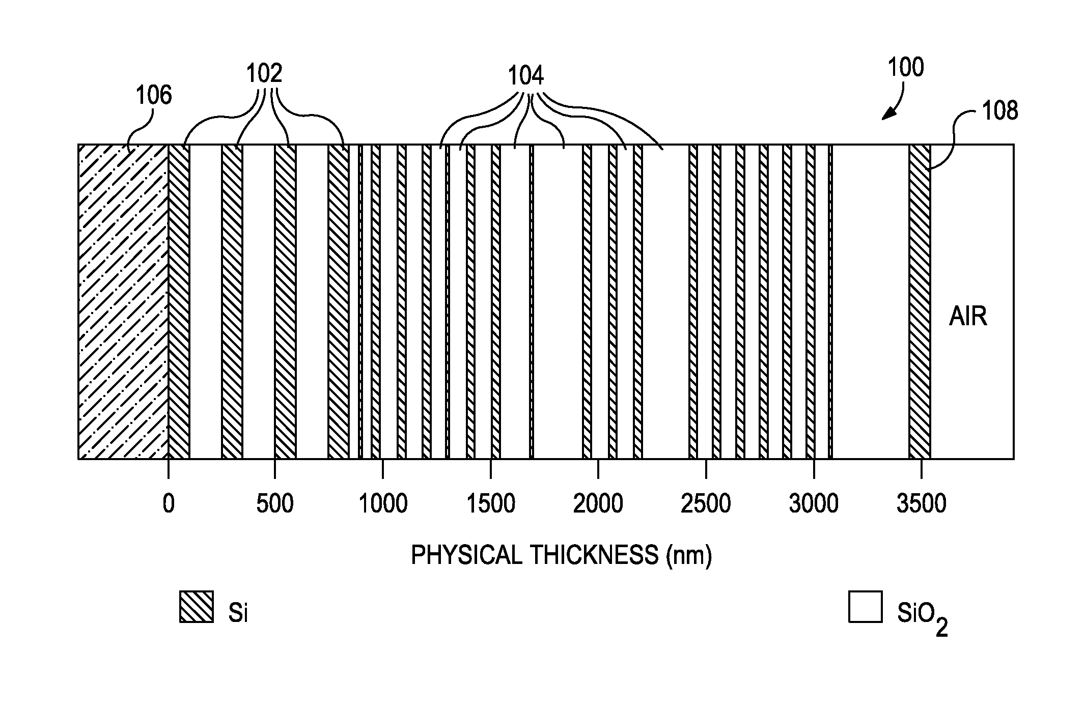
[0015]The present invention relates to optical analysis systems and, in particular, to systems and methods that employ optical analysis systems to inspect and monitor the internals of a pipeline.

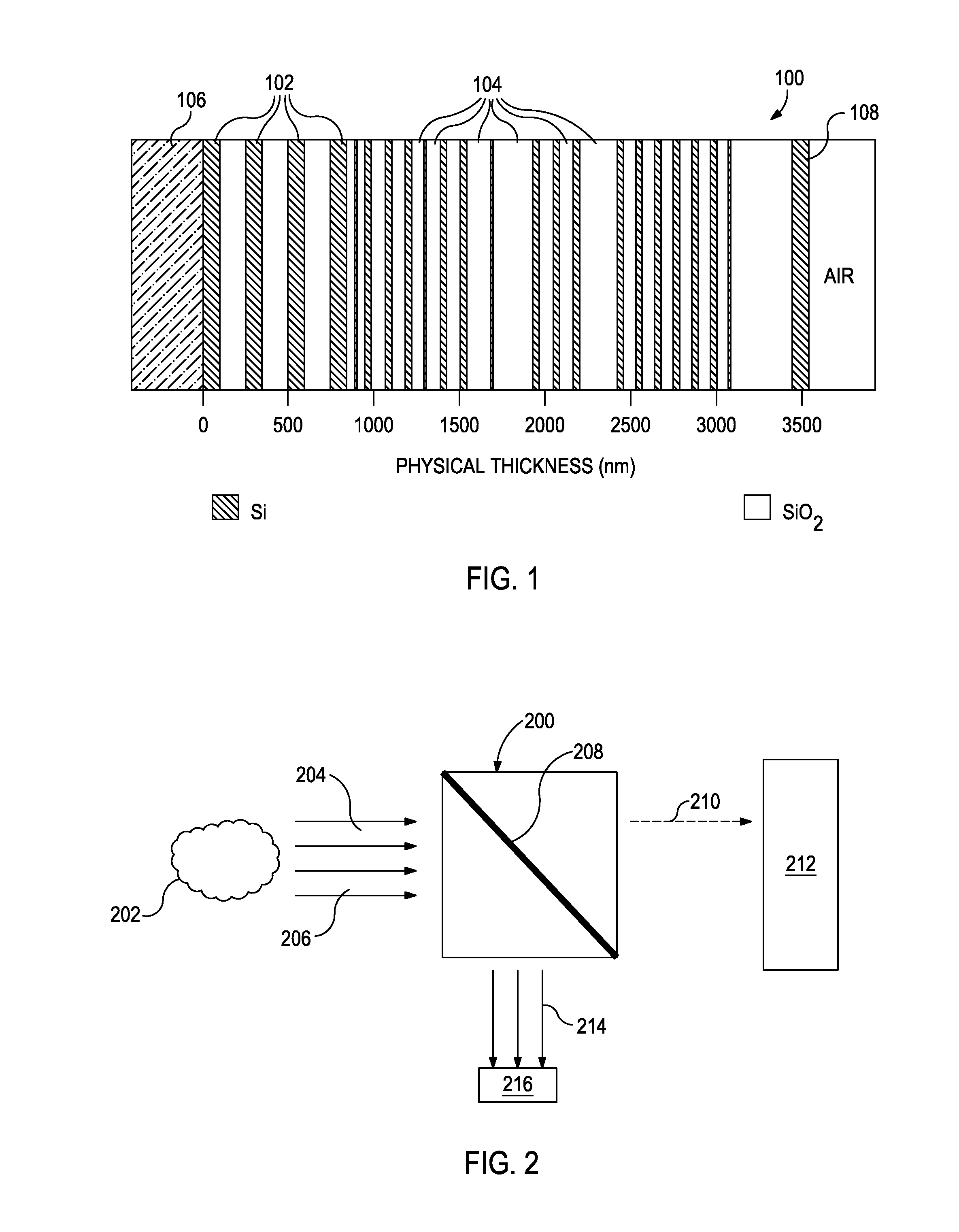
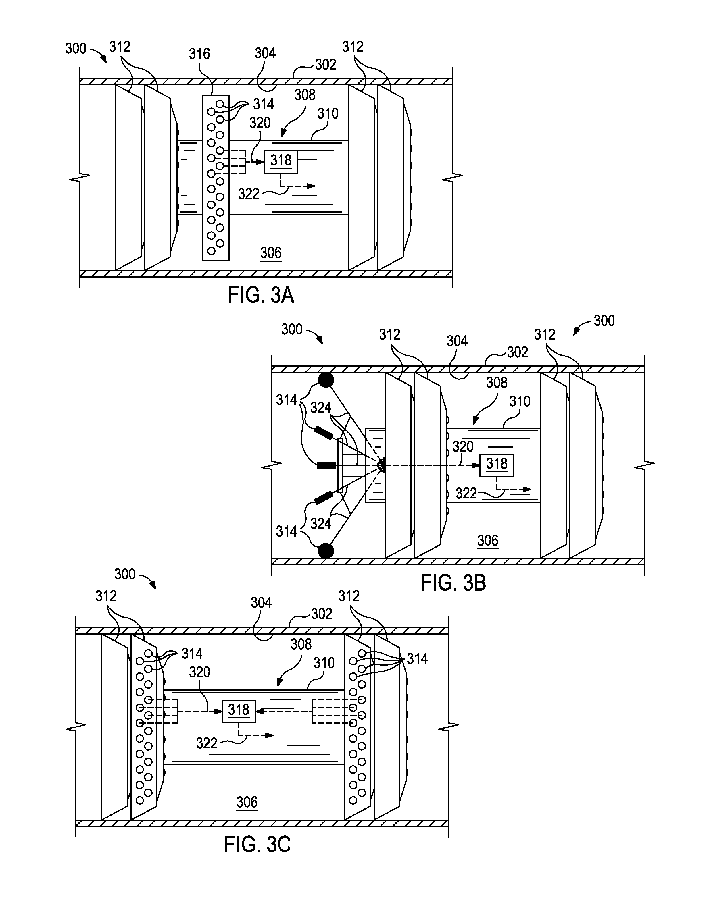
[0016]The exemplary systems and methods described herein employ various configurations of optical computing devices, also commonly referred to as “opticoanalytical devices,” for the inspection and monitoring of the internals of a pipeline, including the inner radial surface of the pipeline and the fluid flowing therein. The optical computing devices may be arranged or otherwise installed on a movable inline inspection device, also known as a “pig”. A significant and distinct advantage of the disclosed optical computing devices, which are described in more detail below, is that they can be configured to specifically detect and / or measure a particular component or characteristic of interest of a chemical composition or other substance, thereby allowing qualitative and / or quantitative analyses ...


PUM


Abstract

Disclosed are systems and methods for inspecting and monitoring an inner surface of a pipeline. One system includes a pig arranged within the pipeline and having a housing that defines a conduit therein for providing fluid communication through the pig, one or more optical computing devices arranged on the conduit for monitoring a bypass fluid flowing through the conduit. The one or more optical computing devices including at least one integrated computational element configured to optically interact with the bypass fluid and generate optically interacted light, and at least one detector arranged to receive the optically interacted light and generate an output signal corresponding to a characteristic of the bypass fluid. A signal processor is communicably coupled to the at least one detector of each optical computing device for receiving the corresponding output signals and determining the characteristic of the fluid.

Description

BACKGROUND[0001]The present invention relates to optical analysis systems and, in particular, systems and methods that employ optical analysis systems to inspect and monitor the internals of a pipeline.[0002]In the oil and gas industry, a tool known as a “pig” refers to any of a variety of movable inline inspection devices that are introduced into and conveyed (e.g., pumped, pushed, pulled, self-propelled, etc.) through a pipeline or a flow line. Pigs often serve various basic functions while traversing the pipeline, including cleaning the pipeline to ensure unobstructed fluid flow and separating different fluids flowing through the pipeline. Modern pigs, however, can be highly sophisticated instruments that include electronics and sensors employed to collect various forms of data during the trip through the pipeline. Such pigs, often referred to as smart pigs or inline inspection pigs, can be configured to inspect the internals or interior of the pipeline, and capture and record sp...

Claims


Application Information

Patent Timeline
IPC IPC(8): G01N21/85G01N21/75
CPCG01N21/85G01N21/31G01N21/954G01J3/02G01N21/17G01N21/27G01M3/005G01M3/38
Inventor TUNHEIM, OLAFREESE, ROBERT P.ABNEY, LAURENCE J.JONES, CHRISTOPHER M.MACLENNAN, JAMES R.
Owner HALLIBURTON ENERGY SERVICES INC
Why Eureka
Try Eureka