
Systems and Methods for Real Time Monitoring of Gas Hydrate Formation

a technology of gas hydrate and monitoring system, which is applied in the direction of optical prospecting, instruments, and borehole/well accessories, etc., can solve the problems of not being able to perform operations in real time or near real time, taking hours to days to complete, and not allowing real-time or near real-time analysis capabilities

Active Publication Date: 2014-06-19
HALLIBURTON ENERGY SERVICES INC
View PDF7 Cites 24 Cited by
  • Summary
  • Abstract
  • Description
  • Claims
  • Application Information

AI Technical Summary

Benefits of technology

The present invention is about monitoring drilling fluids to detect the formation of gas hydrates. The invention includes a system that includes an optical computing device and a detector that can optically interact with the drilling fluid and detect the gas hydrates. The system can also generate a signal corresponding to the characteristics of the gas hydrates. The invention also includes a method to detect the concentration of gas hydrates and initiate corrective actions when the concentration reaches a certain level. Overall, the invention can provide a reliable and efficient way to monitor drilling fluids and prevent accidents during drilling operations.

Problems solved by technology

Depending on the analysis required, however, such an approach can take hours to days to complete, and even in the best case scenario, a job will often be completed prior to the analysis being obtained.
Although off-line, retrospective analyses can be satisfactory in certain cases, but they nonetheless do not allow real-time or near real-time analysis capabilities.
As a result, proactive control of drilling operations cannot take place, at least without significant process disruption occurring while awaiting the results of the analysis.
Off-line, retrospective analyses can also be unsatisfactory for determining true characteristics of a drilling fluid since the characteristics of the extracted sample of the drilling fluid oftentimes changes during the lag time between collection and analysis, thereby making the properties of the sample non-indicative of the true chemical composition or characteristic.

Method used


Image

  • Systems and Methods for Real Time Monitoring of Gas Hydrate Formation
  • Systems and Methods for Real Time Monitoring of Gas Hydrate Formation
  • Systems and Methods for Real Time Monitoring of Gas Hydrate Formation

Examples


Embodiment Construction

[0015]The present invention relates to methods for monitoring drilling fluids and, more specifically, to systems and methods for monitoring a drilling fluid for the formation of gas hydrates.

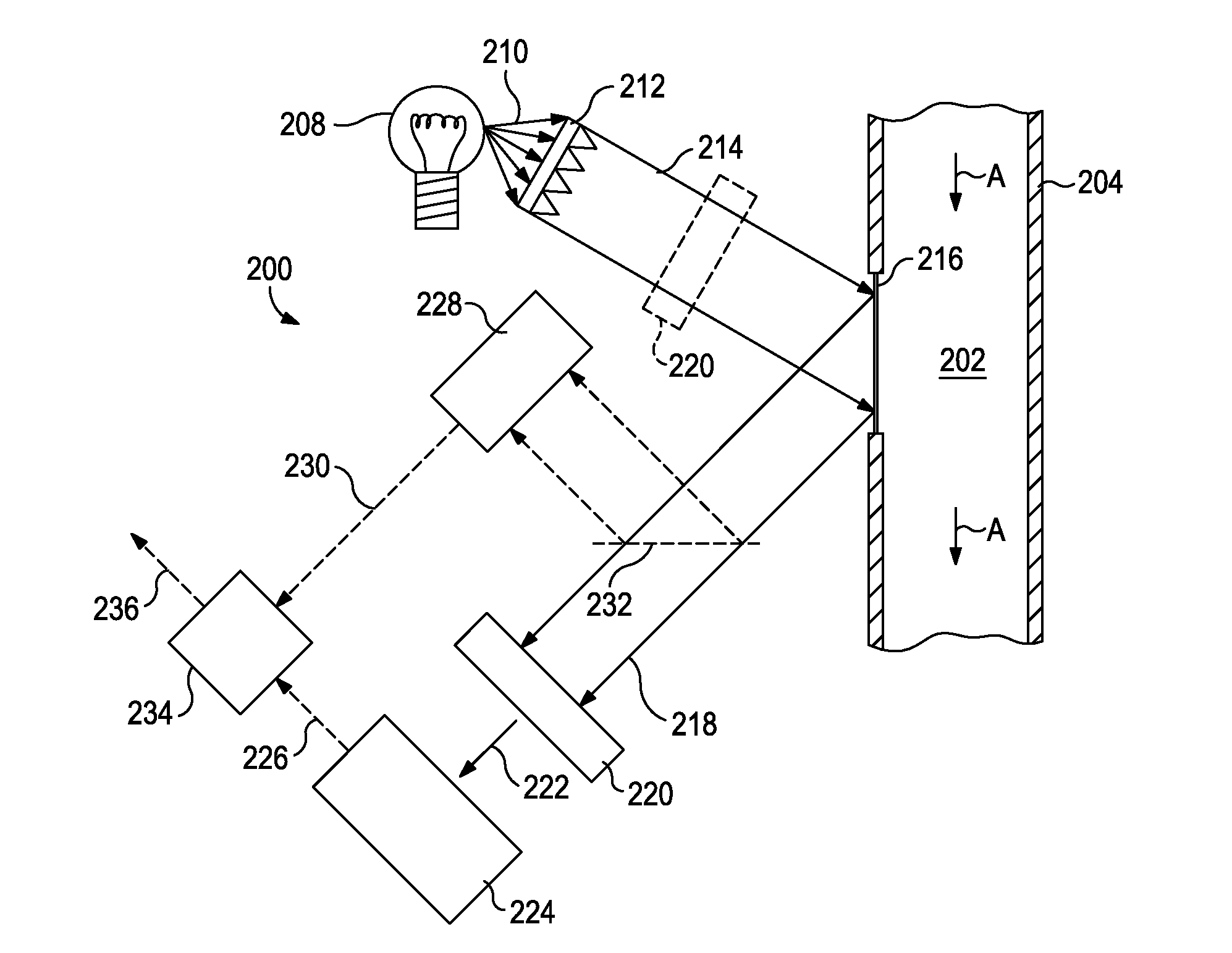
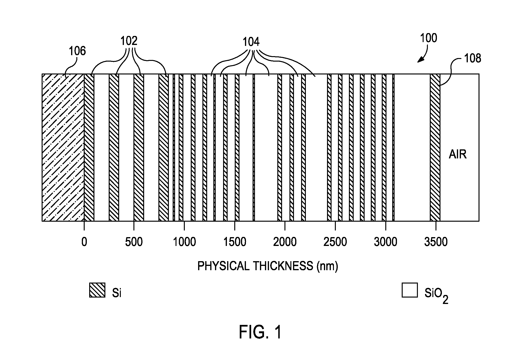
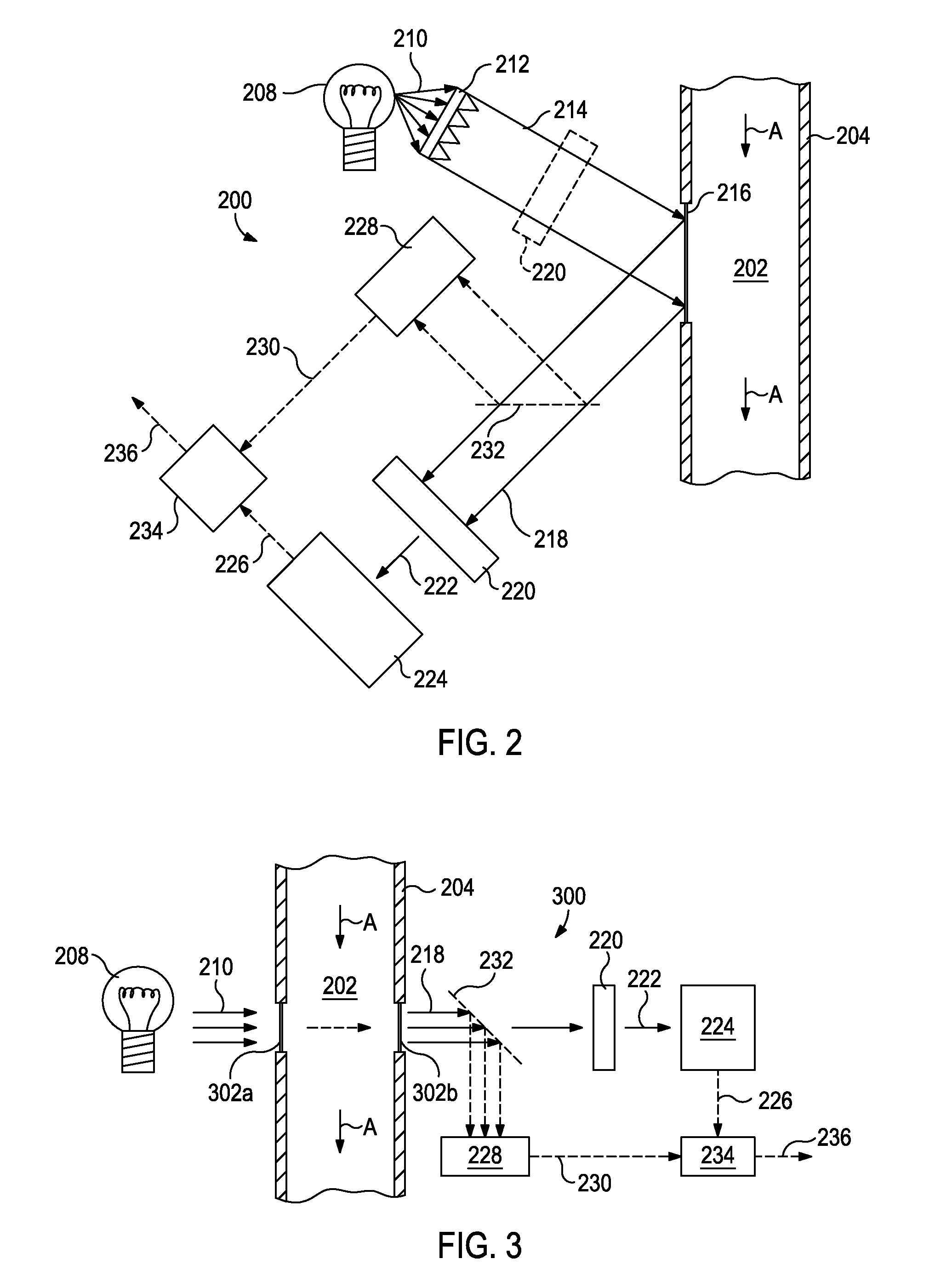
[0016]The exemplary systems and methods described herein employ various configurations of optical computing devices, also commonly referred to as “opticoanalytical devices,” for the real-time or near real-time monitoring of a fluid, such as a drilling fluid or a completion fluid. In operation, the exemplary systems and methods may be useful and otherwise advantageous in determining one or more properties or characteristics of the fluid, such as a concentration of one or more components or substances present within the fluid. The optical computing devices, which are described in more detail below, can advantageously provide real-time fluid monitoring that cannot presently be achieved with either onsite analyses at a job site or via more detailed analyses that take place in a laboratory. A signifi...


PUM


Abstract

Disclosed are systems and methods for monitoring a drilling fluid for the formation of gas hydrates. One system includes a borehole containing a drilling fluid being circulated therethrough, a first optical computing device arranged in the borehole and having at least one integrated computational element configured to optically interact with the drilling fluid and detect one or more gas hydrates present therein, and at least one detector arranged to receive optically interacted light generated from optical interaction between the at least one integrated computational element and the drilling fluid, the at least one detector being configured to generate a first output signal corresponding to a characteristic of the one or more gas hydrates.

Description

BACKGROUND[0001]The present invention relates to methods for monitoring drilling fluids and, more specifically, to systems and methods for monitoring a drilling fluid for the formation of gas hydrates.[0002]During the drilling of a hydrocarbon-producing well, a drilling fluid or mud is continuously circulated from the surface down to the bottom of the hole being drilled and back to the surface again. The drilling fluid serves several functions, one of them being to transport wellbore cuttings up to the surface where they are separated from the drilling fluid. Another function of the drilling fluid is to provide hydrostatic pressure on the walls of the drilled borehole so as to prevent wellbore collapse and the resulting influx of gas or liquid from the formations being drilled. For several reasons, it can be important to precisely know the characteristics and chemical composition of such drilling fluids.[0003]Typically, the analysis of drilling fluids has been conducted off-line usi...

Claims


Application Information

Patent Timeline
Patent Type & Authority Applications(United States)
IPC IPC(8): G01V8/02G05D7/06G06F15/00
CPCG01V8/02G06F15/00G05D7/0617G01V8/12E21B21/00G01N21/31G01N21/85E21B21/08
Inventor JAMISON, DALE E.ALMOND, STEPHEN W.
Owner HALLIBURTON ENERGY SERVICES INC
Learn More