Eureka AIR delivers breakthrough ideas for toughest innovation challenges, trusted by R&D personnel around the world.

Disk spray device

Inactive Publication Date: 2014-03-27
OAV EQUIP & TOOLS
View PDF1 Cites 0 Cited by
  • Summary
  • Abstract
  • Description
  • Claims
  • Application Information

AI Technical Summary

Benefits of technology

The invention is a spray device for disks that allows for a wider spraying range and prevents the area underneath the water mist from getting damp.

Problems solved by technology

Since the water mist is usually sprayed through the nozzles, the spraying range of the water mist is limited to a small area directly in front of the nozzles.
Furthermore, if a conventional spray device is used, the area under the mist may become wet and slippery.
When people walk through the water mist, their faces, glasses or clothes can also get wet.
However, the distribution of the water mist is still limited in the direction right in front of the fan, and thus only the area in front of the fan is humidified and / or cooled.
Besides, such combination sucks the air mainly from behind the fan.
Warm air in an upper part of a building, which may be a distance above the fan combination, is hardly sucked by the fan, thus the humidity and temperature is not uniformly distributed in the building.
Moreover, when the water mist is hit by the direct air flow of the fan, the droplets of the water mist will merge and form bigger droplets which will eventually fall on the floor, making the floor wet and slippery.

Method used


Image

  • Disk spray device
  • Disk spray device
  • Disk spray device

Examples


Embodiment Construction

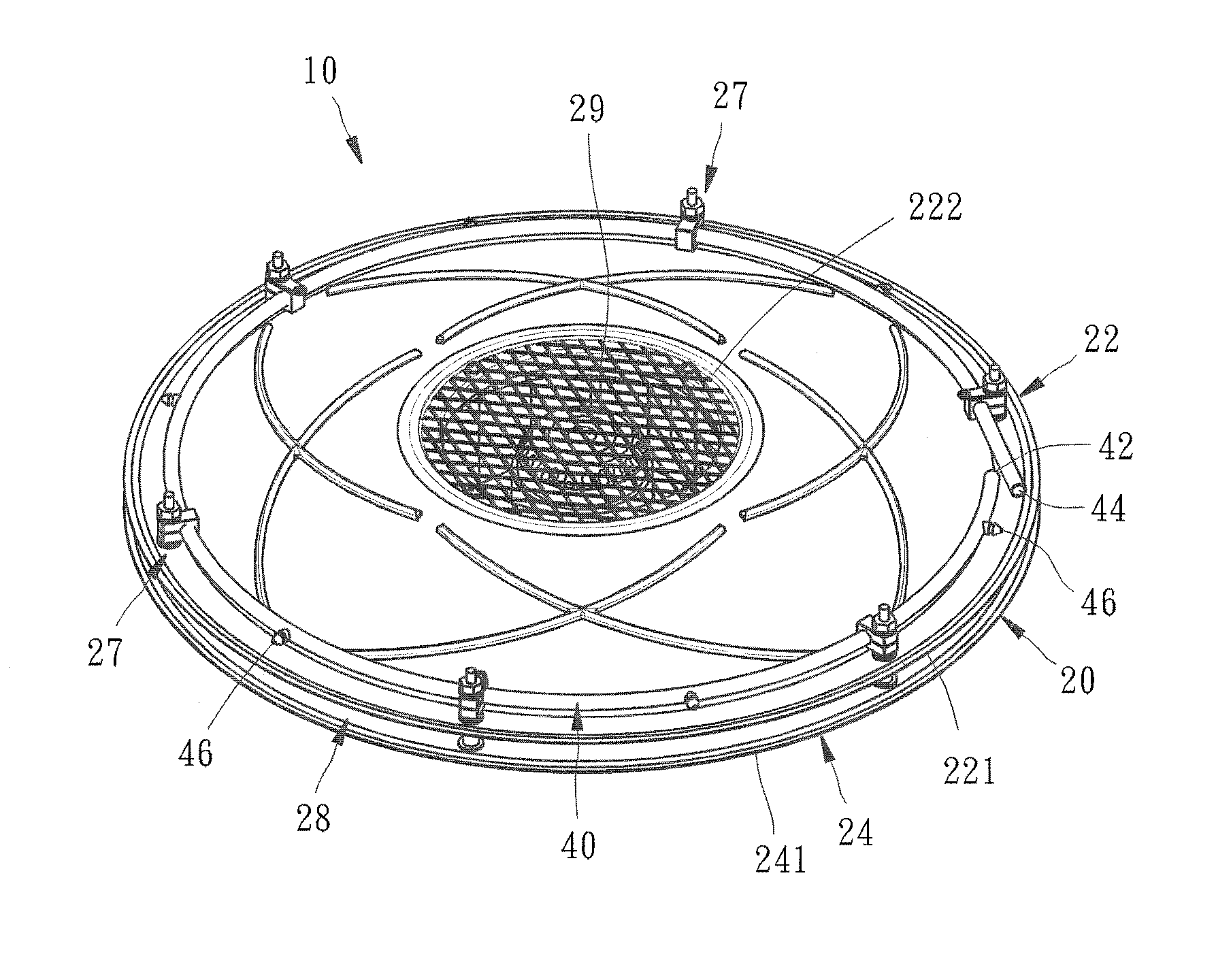
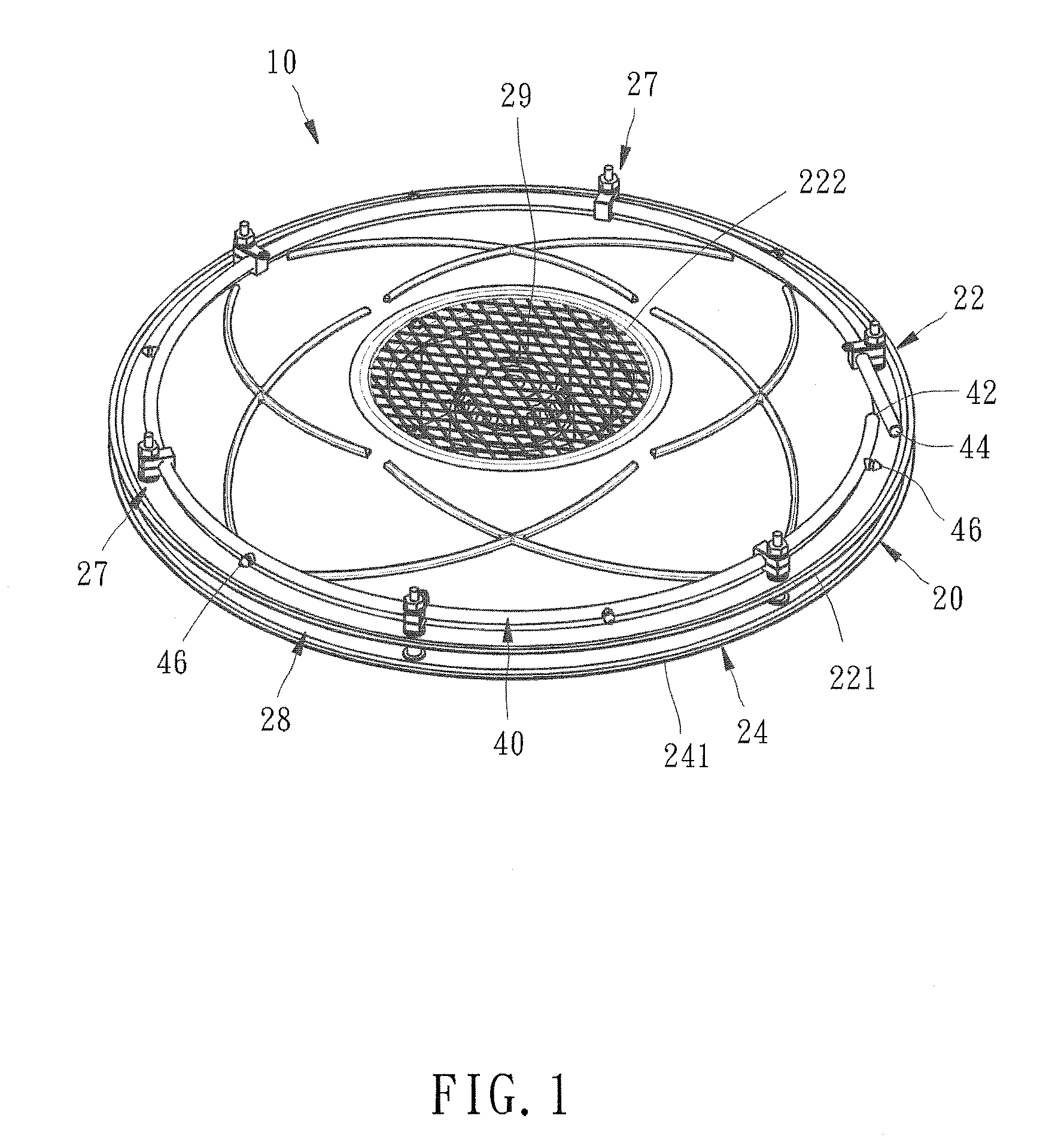
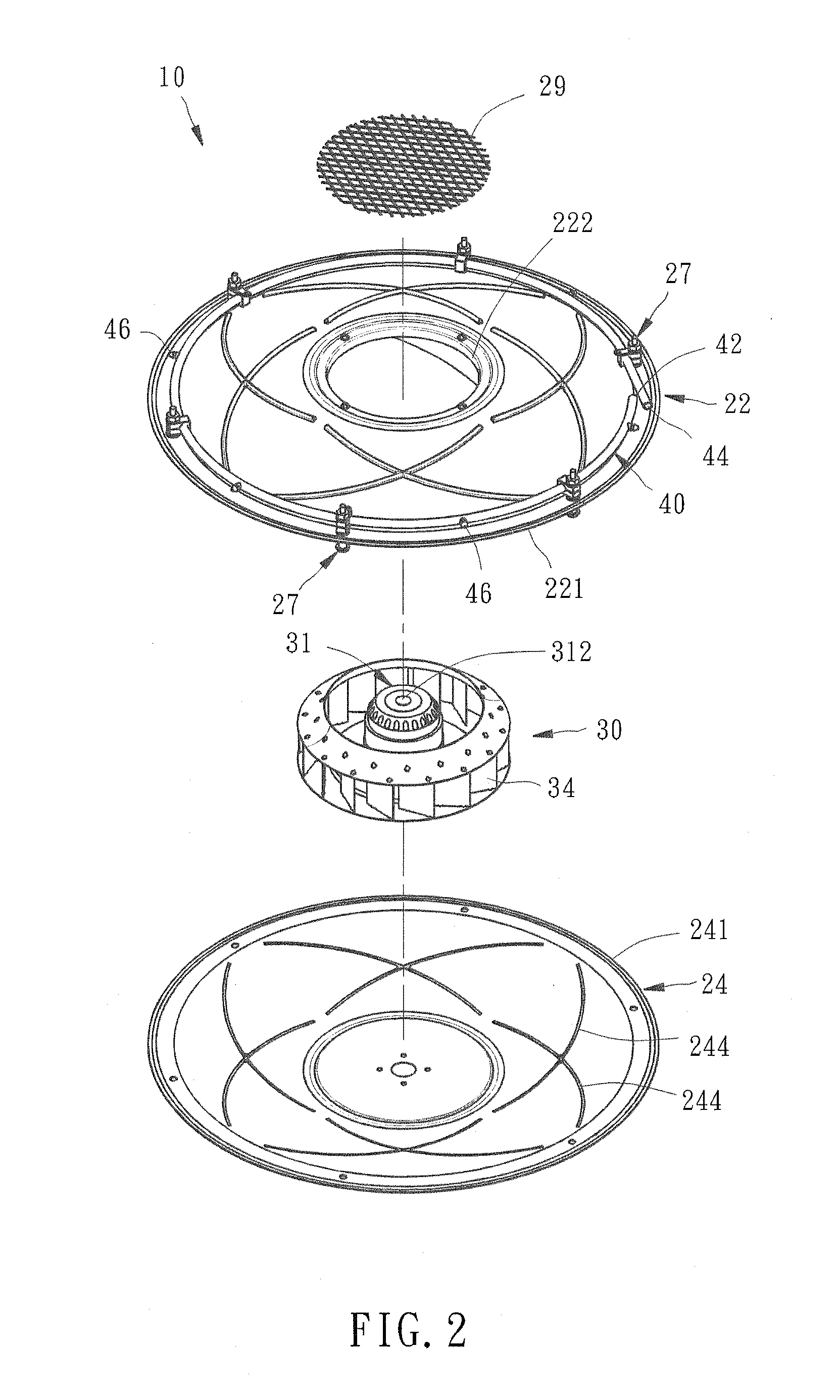
[0019]As shown in FIGS. 1 through 4, a disk spray device 10 in accordance with the preferred embodiment of the present invention comprises a shell 20, a fan 30, and a spray tube 40 with nozzles 46. The fan 30 can be a centrifugal fan or an axial fan.

[0020]The shell 20 includes an upper shell body 22, a lower shell body 24, and four guide plates 26. The lower shell body 24 and the upper shell body 22 are similar in configuration. The upper shell body 22 has a top air inlet 222, a bottom opening 221 and four pairs of smoothly curved locating grooves 224 at the inner side, as shown in FIG. 3. The two locating grooves 224 of each pair are intersected with each other, and respectively extend in a curved matter from locations adjacent to the top air inlet 222 in clockwise and counterclockwise directions. The lower shell body 24 has a top opening 241 and is fastened to the upper shell body 22 by several fasteners 27 through a number of spacers in such a way that the openings 221 and 241 ar...


PUM


Abstract

A disk spray device includes a shell having a top air inlet and an annular air outlet, a fan for sucking air from above the device and distributing the air through the annular air outlet to generate an air cushion around the shell, and a spray tube mounted around an outer periphery of the shell and having a plurality of nozzles adjacent to the air outlet of the shell. The spray tube is adapted to be connected with a water supply device such that water running in the spray tube can be sprayed into water mist through the nozzles of the spray tube. The water mist can be further radially delivered far away by the flow of air exhausted out of the annular air outlet of the shell by the fan.

Description

CROSS-REFERENCE TO RELATED APPLICATION[0001]This patent application is a continuation-in-part of U.S. patent application Ser. No. 12 / 959,514 filed Dec. 3, 2012 entitled “Disk Spray Device”, the entire disclosure of which is incorporated herein by reference.BACKGROUND OF THE INVENTION[0002]1. Field of the Invention[0003]The present invention relates generally to a spray device, and more specifically to a disk spray device which utilizes a fan to cover a broader area with water mist.[0004]2. Description of the Related Art[0005]Under a dry or hot environment, a spray device set at a predetermined height may be used to spray water mist to increase the air humidity or lower the temperature. A conventional spray device generally includes a water pipe and a plurality of nozzles connected with the water pipe for discharging water in the form of water mist. Since the water mist is usually sprayed through the nozzles, the spraying range of the water mist is limited to a small area directly in...

Claims


Application Information

Patent Timeline
IPC IPC(8): B05B7/00
CPCB05B7/00B05B3/022B05B7/0081
Inventor LIN, CHIU-HSIANGANKIRSKY, MIKHAIL
Owner OAV EQUIP & TOOLS
Why Eureka
Eureka Blog
Learn More