Quick response code display for communications and error handling

a technology of communication and error handling, applied in the field of interface devices, can solve the problems of burdensome monitoring of multiple lcd screens on multiple interface panels, limited information on the lcd display, and inability to increase the size of the lcd display,

Inactive Publication Date: 2014-03-27
EATON CORP
View PDF7 Cites 37 Cited by
  • Summary
  • Abstract
  • Description
  • Claims
  • Application Information

AI Technical Summary

Benefits of technology

The patent describes a system that allows a computer to receive data from multiple devices, like industrial motors, and generate a barcode based on that data. The barcode is then displayed on a screen for easy identification. The technical effect of this system is that it provides a more efficient and organized way of displaying and managing the status of multiple devices.

Problems solved by technology

An LCD display may be limited in size and therefore be limited in the amount of information it can convey to the user.
Increasing the size of the LCD display may not be practical, given the limited amount of room available on the interface panel.
In addition, when interfacing with multiple devices, monitoring multiple LCD screens on multiple interface panels may be burdensome and inefficient.

Method used


Image

  • Quick response code display for communications and error handling
  • Quick response code display for communications and error handling
  • Quick response code display for communications and error handling

Examples


Embodiment Construction

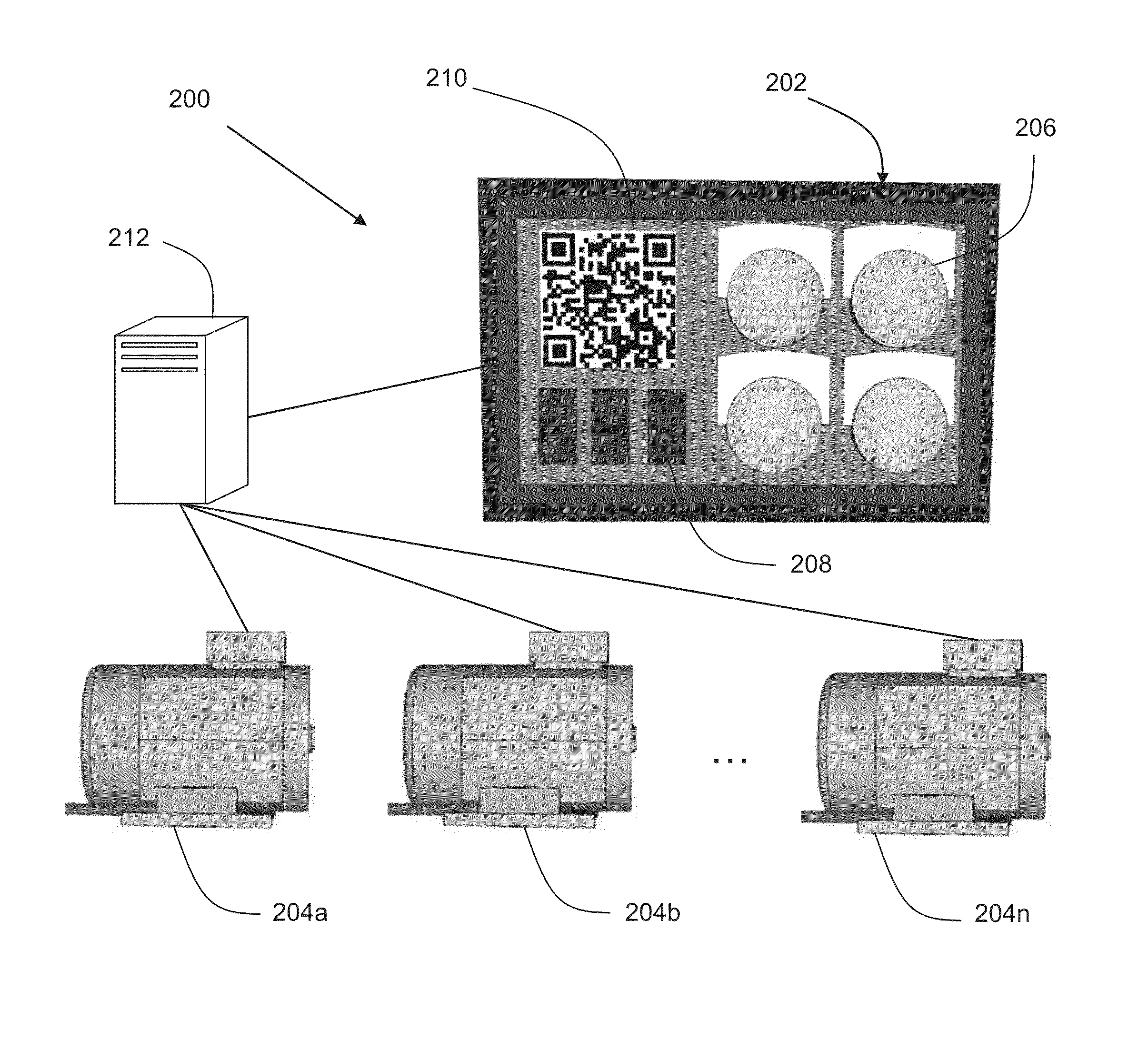
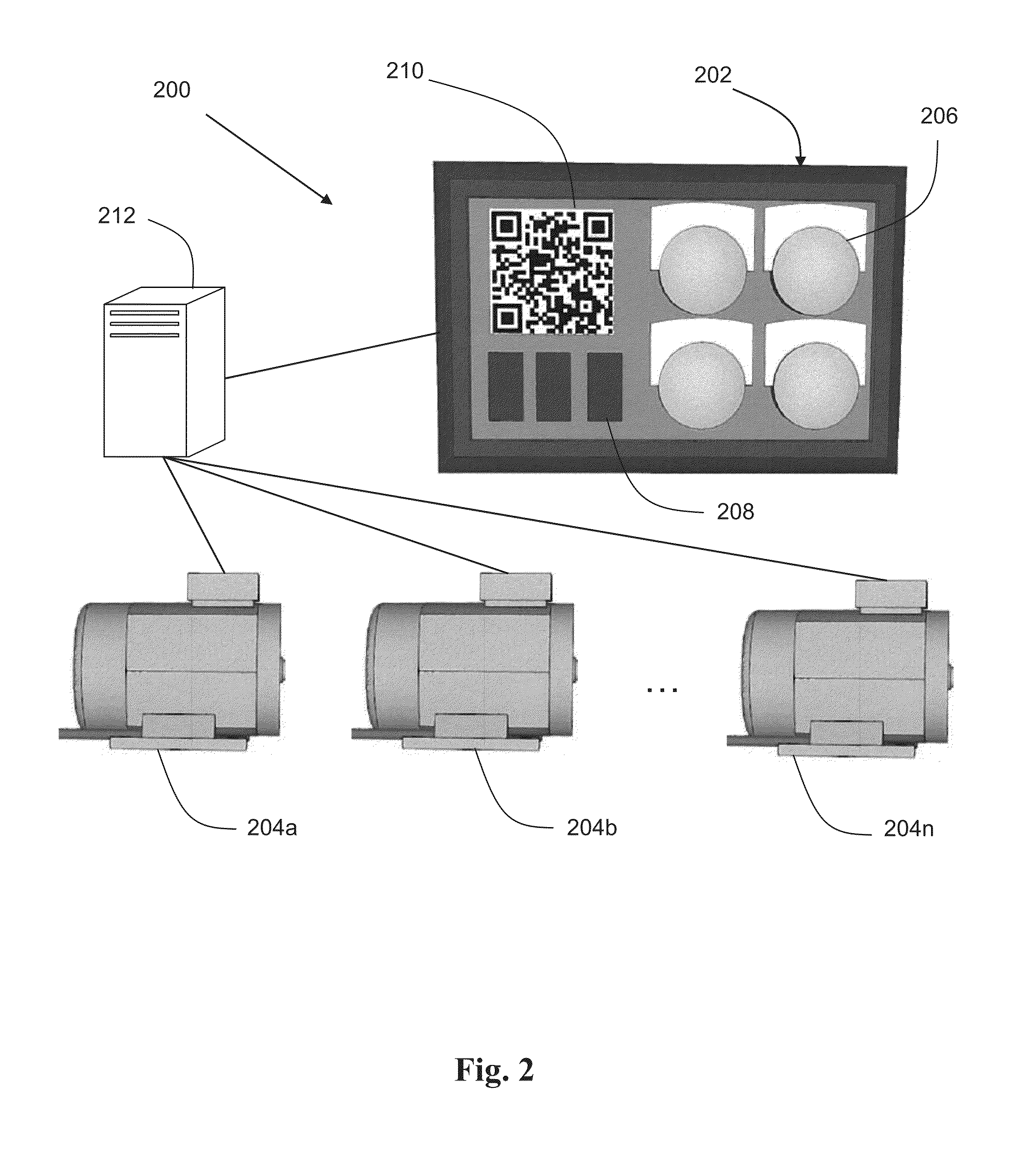
[0015]FIG. 2 is an example system 200 for communicating status information, including both event-based and non-event-based information, associated with a plurality of devices according to one embodiment of the present disclosure. System 200 includes an interface 202 operatively connected to multiple devices 204a, 204b, and 204n (hereinafter referred to as devices 204). Interface 202 communicates with devices 204 and enables a user to monitor and interface with devices 204. For example, interface 202 may be used as an interface panel in an industrial setting for monitoring and interfacing with an industrial motor. In the illustrated embodiment, interface 202 includes a plurality of buttons 206 for receiving input from a user. In addition, the interface 202 includes LEDs 208 and a display screen 210 for communicating messages to the user. In an alternative embodiment, the interface 202 includes one or more switches, dials, a keyboard, or other input device in addition to, or instead o...


PUM


Abstract

A system for communicating status information associated with a plurality of devices has a display controller communicatively coupled to the plurality of devices, configured to receive data associated with at least one of the plurality of devices. The display controller is also configured to generate at least one barcode representative of the received data. The system has a display screen communicatively coupled to the display controller. The display screen is configured to display the at least one barcode.

Description

FIELD OF INVENTION[0001]The present disclosure relates to interface devices. More particularly, the present disclosure relates to interface devices for communicating status information via a quick response code display.BACKGROUND[0002]Interface panels are used in a variety of industries and applications for interfacing various mechanical devices. Interface panels may have buttons or other controls for receiving input from a user as well as outputs, such as LEDs or an LCD display, for conveying information to a user. In certain applications, such as in an industrial power application, multiple interface panels may be combined to form a larger control center for interfacing with multiple devices. FIG. 1 illustrates an example prior art interface panel 100 for interfacing with a mechanical device. Interface panel 100 has a plurality of buttons 102, a plurality of LEDs 104, and an LCD display 106.[0003]An LCD display may be limited in size and therefore be limited in the amount of infor...

Claims


Application Information

Patent Timeline
IPC IPC(8): G06T11/20
CPCG06F3/147G09G2380/06
Inventor CZAPAR, MATTHEW
Owner EATON CORP
Why Eureka
Try Eureka