Supercharge Your Innovation With Domain-Expert AI Agents!

Stereoscopic video imaging system and synchronous control method

a video imaging and synchronization control technology, applied in the field of synchronization control methods in the stereoscopic video imaging system, can solve the problems of large shooting equipment, time and labor to check the setting values, etc., and achieve the effect of saving time and effor

Active Publication Date: 2014-03-27
SONY CORP
View PDF24 Cites 3 Cited by
  • Summary
  • Abstract
  • Description
  • Claims
  • Application Information

AI Technical Summary

Benefits of technology

The patent aims to save time and effort in preparing two cameras to capture stereoscopic videos. The technical effect is to simplify the process of setting up the cameras to capture video in a more efficient manner.

Problems solved by technology

However, in the related art, a lot of cables for connecting two cameras are used and shooting equipment becomes large.
In addition, it takes time and labor to check whether the setting values are actually the same or not in the two cameras.

Method used


Image

  • Stereoscopic video imaging system and synchronous control method
  • Stereoscopic video imaging system and synchronous control method
  • Stereoscopic video imaging system and synchronous control method

Examples


Embodiment Construction

[0030]Hereinafter, an example for carrying out the present disclosure (hereinafter, also referred to as “embodiment”) will be described with reference to the attached drawings. Description will be given in the following order. It should be noted that in the drawings, common constituent elements are denoted by the same reference symbols and overlapping description will be omitted.

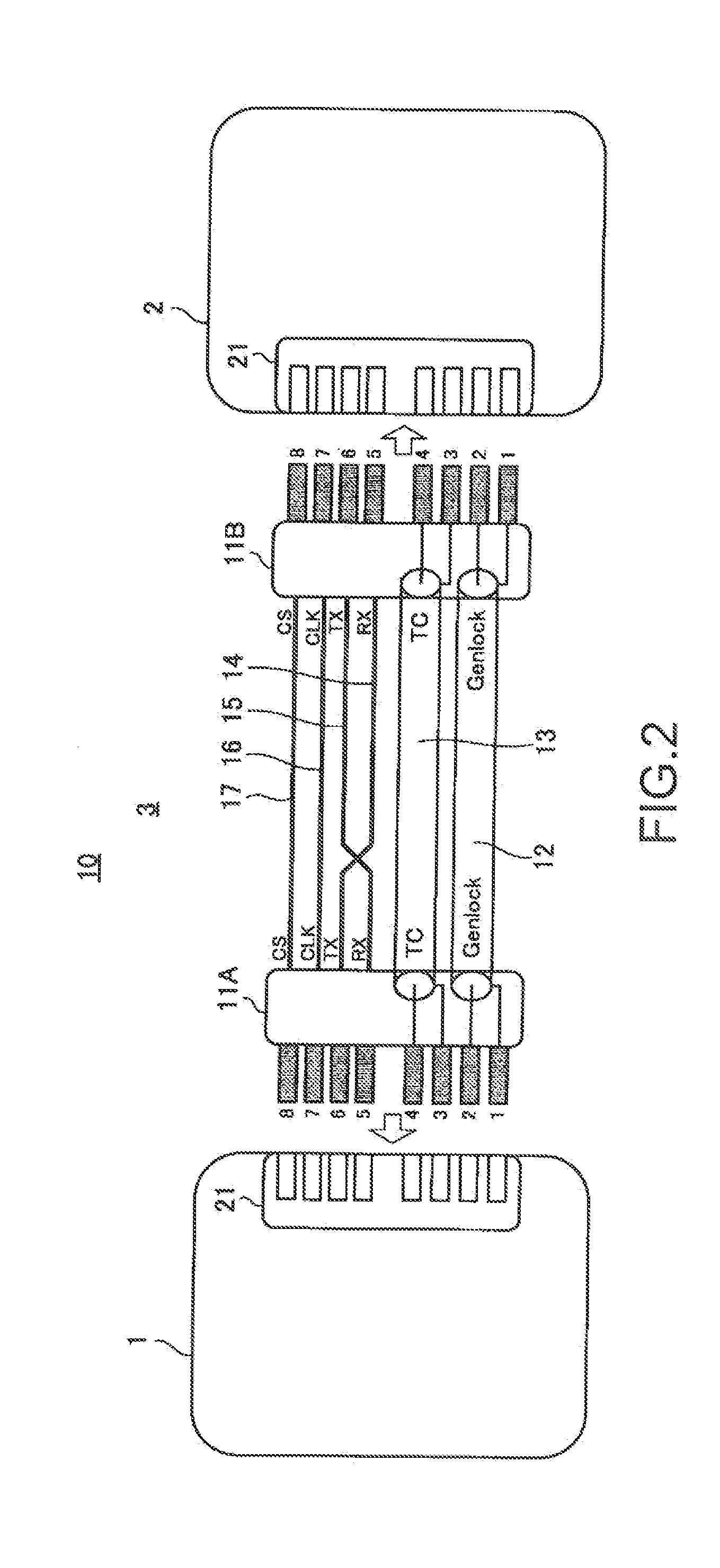
1. One Embodiment (example in which two imaging apparatuses are connected by single dedicated cable)

2. Others (example of reflecting camera setting value from main imaging apparatus to sub-imaging apparatus, and example of recording start and reproduction stop)

1. One Embodiment

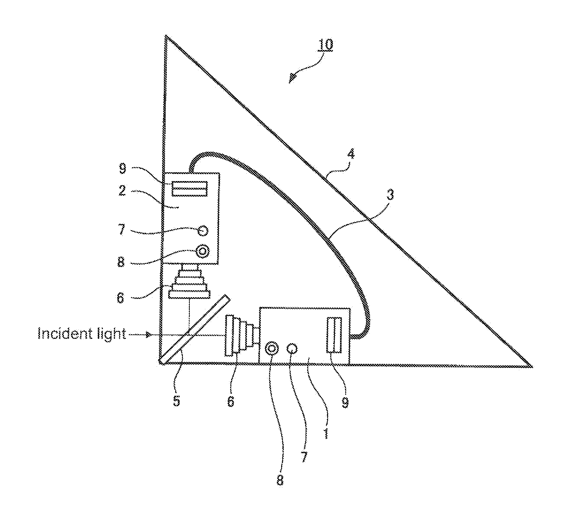
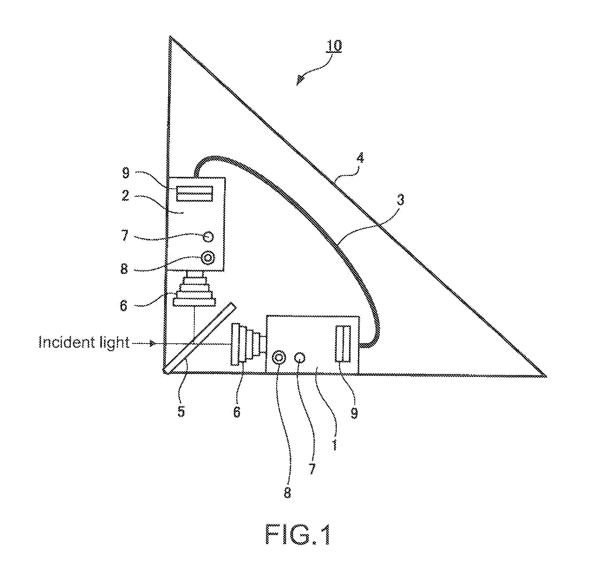
External Structure of Stereoscopic Video Imaging System

[0031]In this embodiment, an example applied to a stereoscopic video imaging system 10 in which two imaging apparatuses (cameras) are connected to each other by a single dedicated cable to capture a stereoscopic video will be described (hereinafter, referred to as “this example”).

[...


PUM


Abstract

A stereoscopic video imaging system includes a first imaging apparatus and a second imaging apparatus coupled to the first imaging apparatus and arranged to take a 3D image. A single cable connects the first imaging apparatus to the second imaging apparatus. A switching device selects one of the first and second imaging apparatuses to be a main imaging apparatus and the remaining imaging apparatus to be a sub imaging apparatus. The main imaging apparatus is enabled to generate a synchronization signal, the synchronization signal being communicated to the sub imaging apparatus through the single cable.

Description

TECHNICAL FIELD[0001]The present disclosure relates to a stereoscopic video imaging system and a synchronous control method that are suitable for use in the case where, for example, a stereoscopic video (3D video) is generated from videos captured with two cameras.BACKGROUND ART[0002]From the past, there has been a technique of generating a stereoscopic video (3D video) that can be stereoscopically viewed by a user with use of videos of the same subject. Those videos are captured with two cameras installed in accordance with parallax of right and left eyes of the user.[0003]As an example of the stereoscopic video imaging system, there is a system in which videos of reflected light and transmitted light are captured with right and left cameras through a half mirror mounted to a mount called rig. When a stereoscopic video is captured using a rig, it is necessary for the two cameras used to coincide with each other in settings thereof and to be synchronized with each other in order to ...

Claims


Application Information

Patent Timeline
Patent Type & Authority Applications(United States)
IPC IPC(8): H04N13/02H04N13/239
CPCH04N13/0239H04N13/0296G03B35/08G03B2206/00H04N13/239H04N13/296H04N23/66
Inventor YOSHIZAWA, YASUO
Owner SONY CORP
Features
  • R&D
  • Intellectual Property
  • Life Sciences
  • Materials
  • Tech Scout
  • Unparalleled Data Quality
  • Higher Quality Content
  • 60% Fewer Hallucinations
Learn More