Method, transport apparatus, and system for detecting submarine optical cable line

a technology of optical cable and transport apparatus, applied in the field of optical communication technologies, can solve the problems of submarine optical cable and device failures that have a huge impact on communication, difficult to identify pump failure events, and difficult to distinguish whether the cable is broken or the next optical repeater fails

Active Publication Date: 2014-03-27
HUAWEI MARINE NETWORKS CO LTD
View PDF22 Cites 17 Cited by
  • Summary
  • Abstract
  • Description
  • Claims
  • Application Information

AI Technical Summary

Benefits of technology

[0029]An embodiment of the present invention also provides a transport apparatus for detecting a submarine optical cable line, where the apparatus can support detecting of a status of an optical cable, and can also clearly distinguish a failure mode beyond the line of sight of a backscattered signal in scenarios of long spans.
[0030]An embodiment of the present invention also provides a system for detecting a submarine optical cable line, where the system can support detecting of a status of an optical cable, and can also clearly distinguish a failure mode beyond the line of sight of a backscattered signal in scenarios of long spans.

Problems solved by technology

Failures of submarine optical cables and devices have a huge impact on communication.
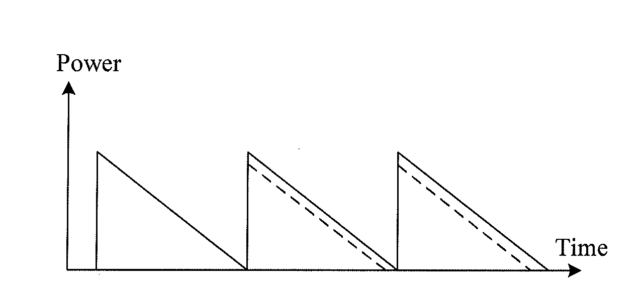
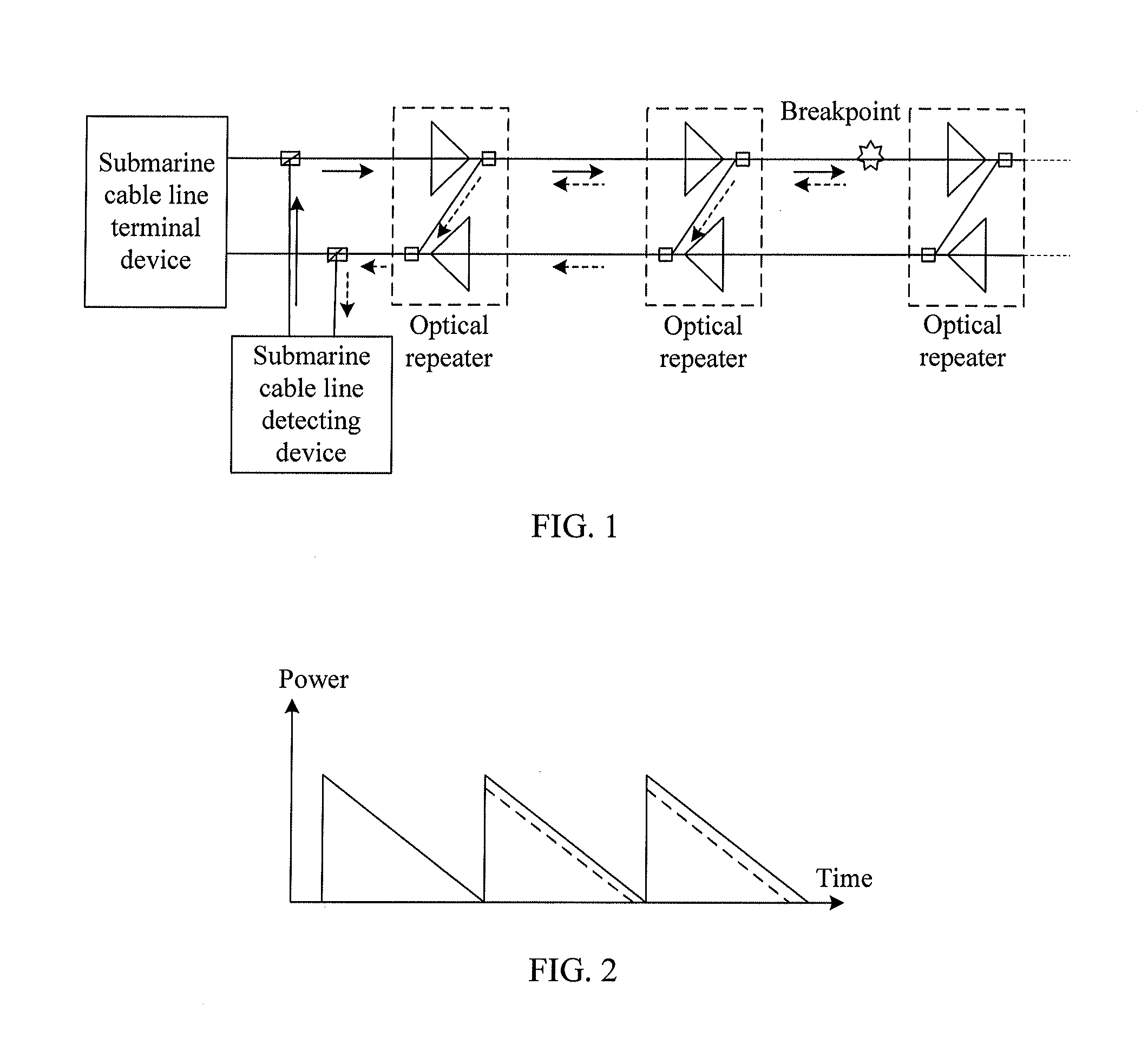
The detection curve cannot reflect changes of the gain and output power of the optical repeater in the line, and it is difficult to identify a pump failure event.
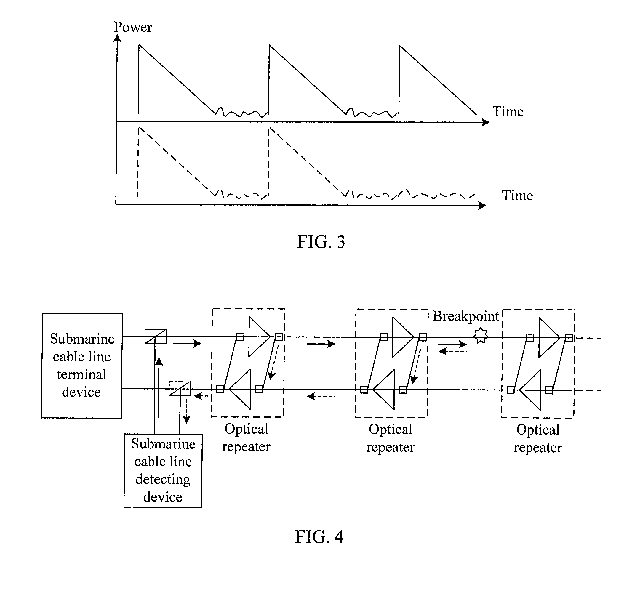
The wave part in the lower part of FIG. 3 is similar to the wave part in the upper part of FIG. 3, and therefore, it is difficult to distinguish whether the cable is broken or the next optical repeater fails.
The wave part in the lower part of FIG. 3 is similar to the wave part in the upper part of FIG. 3, but it is still difficult to distinguish the two failure modes.
Likewise, for a submarine optical functional module, for example, an optical equalizer or an optical splitter, failures cannot be located accurately, and as a result, a performance detecting and failure locating cannot be performed for the submarine device accurately.
With the development of submarine cable transmission technologies, the span distance of the submarine cable in some areas is increased from 70 km to more than 100 km and even to 120-150 km, and the coherent OTDR detection capability already cannot satisfy the requirement for accurately locating a long-span system failure.

Method used


Image

  • Method, transport apparatus, and system for detecting submarine optical cable line
  • Method, transport apparatus, and system for detecting submarine optical cable line
  • Method, transport apparatus, and system for detecting submarine optical cable line

Examples


embodiment 1

[0139]FIG. 13 is a schematic structural diagram of an apparatus for detecting a submarine optical cable line according to Embodiment 1. The first coupling apparatus includes a first coupler 1303 and a first reflector 1304; the second coupling apparatus includes a second coupler 1306; the third coupling apparatus includes a third coupler 1309; and the fourth coupling apparatus includes a fourth coupler 1311 and a fourth reflector 1310. The optical repeater includes a pair of a first amplifier 1301 and a second amplifier 1302 for amplification and arranged in opposite transmission directions; the input end and output end of the first amplifier 1301 are respectively connected to the first coupler 1303 and the second coupler 1306; symmetrically, the input end and output end of the second amplifier 1302 are respectively connected to the fourth coupler 1311 and the third coupler 1309. The first coupler 1303, the second coupler 1306, the third coupler 1309, and the fourth coupler 1311 are ...

embodiment 2

[0151]FIG. 17 is a schematic structural diagram of an apparatus for detecting a submarine optical cable line according to Embodiment 2. The first coupling apparatus includes a first coupler 1703 and a first reflector 1704; the second coupling apparatus includes a second coupler 1706 and a second reflector 1707; the third coupling apparatus includes a third coupler 1709 and a third reflector 1708; and the fourth coupling apparatus includes a fourth coupler 1712 and a fourth reflector 1711. The optical repeater includes a first amplifier 1701 and a second amplifier 1702. The first amplifier 1701 and the second amplifier 1702 are used for amplification and arranged in opposite transmission directions; the input end and output end of the first amplifier 1701 are respectively connected to the first coupler 1703 and the second coupler 1706; symmetrically, the input end and output end of the second amplifier 1702 are respectively connected to the fourth coupler 1712 and the third coupler 1...

embodiment 3

[0162]FIG. 18 is a schematic structural diagram of an apparatus for detecting a submarine optical cable line according to Embodiment 3. The first coupling apparatus includes a first coupler 1803 and a first reflector 1805; the second coupling apparatus includes a second coupler 1806 and a second reflector 1808; the third coupling apparatus includes a third coupler 1809 and a third reflector 1811; and the fourth coupling apparatus includes a fourth coupler 1812 and a fourth reflector 1813. The optical repeater includes a pair of a first amplifier 1801 and a second amplifier 1802 for amplification and arranged in opposite transmission directions; the input end and output end of the first amplifier 1801 are respectively connected to the first coupler 1803 and the second coupler 1806; symmetrically, the input end and output end of the second amplifier 1802 are respectively connected to the third coupler 1809 and the fourth coupler 1812. The first coupler 1803, the second coupler 1806, t...


PUM


Abstract

A method for detecting a submarine optical cable line includes: splitting a detection signal input to a first optical functional unit in an optical functional module of an optical cable line into a first detection signal and a second detection signal; directly coupling and looping back the first detection signal to an output end of a second optical functional unit in a direction opposite to the first optical functional unit to constitute a first loopback path, and outputting a first detection loopback signal; looping back the second detection signal passing through the first optical functional unit to the output end of the second optical functional unit to constitute a second loopback path, and outputting a second detection loopback signal; and detecting a status of the submarine optical cable line according to power of the first detection loopback signal and power of the second detection loopback signal.

Description

CROSS-REFERENCE TO RELATED APPLICATIONS[0001]This application is a continuation of International Application No. PCT / CN2012 / 071485, filed on Feb. 23, 2012, which claims priority to Chinese Patent Application No. 201110139715.1, filed on May 27, 2011, both of which are hereby incorporated by reference in their entireties.FIELD OF THE INVENTION[0002]The present invention relates to the field of optical communication technologies, and in particular, to a method, a transport apparatus, and a system for detecting a submarine optical cable line.BACKGROUND OF THE INVENTION[0003]A submarine cable communication system bears large-capacity communication services between continents. Failures of submarine optical cables and devices have a huge impact on communication. An objective that the submarine cable system pursues constantly is to locate a failure point timely and precisely and accurately reflect a failure mode. A failure locating method based on an optical time-domain reflectometry (OTDR...

Claims


Application Information

Patent Timeline
Patent Type & Authority Applications(United States)
IPC IPC(8): H04B10/077H04B10/80
CPCH04B10/80H04B10/0771H04B10/071
Inventor ZHANG, WENDOUMA, LIPING
Owner HUAWEI MARINE NETWORKS CO LTD
Why Eureka
Try Eureka