Incremental multi-position detection system for a revolving electromagnetic transfer system

a detection system and electromagnetic transfer technology, applied in mechanical conveyors, instruments, measurement devices, etc., can solve the problems of superfluous dedicated sensors for referencing the incremental travel measurement system, inability to produce conveying elements in a more cost-effective manner, and inability to achieve failsafe effects

Inactive Publication Date: 2013-02-14
ROBERT BOSCH GMBH
View PDF8 Cites 19 Cited by
  • Summary
  • Abstract
  • Description
  • Claims
  • Application Information

AI Technical Summary

Benefits of technology

[0006]In contrast to the above, the transportation apparatus according to the invention has the advantages that an incremental travel measurement system can be integrated in an existing guidance system for the conveying element, and can be produced without wear and in a cost-effective manner. According to the invention, this is achieved in that a moveable conveying element which is provided for conveying the product is provided with a grid which extends over a predetermined grid length in the movement direction of the conveying element and has a large number of travel increments. Travel increments of the grid which are situated next to one another can be clearly distinguished from one another by measurement. If the travel increments are selected such that they can be distinguished from one another by measurement without an external energy supply, the conveying element can be of fully passive design entirely without active components, and therefore neither a supply of electrical energy to the conveying element nor a transmission of measurement signals to or from the conveying element is necessary. As a result, the conveying element can not only be produced in a more cost-effective manner, but it is also more fail-safe. A large number of position sensors is arranged along a running path which defines a running distance for the conveying element, the distances between said large number of position sensors being smaller than the grid length. As a result, the incremental travel measurement system can be freely projected, and therefore a minimum number of position sensors can be provided for a given length of the conveying element and the entire system is not unnecessarily expensive. A measurement device is designed to determine a current position of the conveying element on the running path, with the measurement device, when the grid enters and / or exits the measurement region of a position sensor, defining the current position with respect to a reference position, which is derived from the position of the corresponding position sensor, of the conveying element on the running path, monitoring at least one of the position sensors, the conveying element being located in the measurement region of said at least one position sensor, and incrementing or decrementing the current position when a travel increment passes a monitored position sensor. This allows the incremental travel measurement system to be referenced and incremented by means of a single sensor and allows highly dynamic travel measurements, with the reference run making up only a fraction of the total travel distance. Therefore, dedicated sensors for referencing the incremental travel measurement system are superfluous.
[0007]The position sensors can be arranged in a running rail which runs along the running path, and therefore the running rail additionally forms a housing for the position sensors and the transportation apparatus can be of more compact design. As a result, it is possible to dispense with a separate apparatus for accommodating the position sensors.
[0013]In a particular development, the measurement device can be designed to weight the position sensors in the transition region. This prevents jumps in the measurement signal, and therefore the conveying element can be smoothly transferred from one position sensor to the next position sensor with a fluid transition.
[0014]In a further preferred development, the measurement device can have a switching device which is suitable for switching on the monitoring of a position sensor when a measurement signal of the position sensor for detecting the travel increments which is to be switched on has settled within a predetermined tolerance band, and therefore incorrect measurements as the conveying element enters and exits the measurement region of a position sensor are avoided.
[0015]In a particularly preferred embodiment, the switching device can additionally have a presence sensor which is suitable for activating the monitoring of a position sensor when a predetermined portion of the grid is in its measurement region. In this way, the position sensors can be switched on and switched off in a situation-related manner, this considerably reducing the energy consumption in the case of relatively large running rails with a corresponding number of position sensors.

Problems solved by technology

As a result, the conveying element can not only be produced in a more cost-effective manner, but it is also more fail-safe.
Therefore, dedicated sensors for referencing the incremental travel measurement system are superfluous.

Method used


Image

  • Incremental multi-position detection system for a revolving electromagnetic transfer system
  • Incremental multi-position detection system for a revolving electromagnetic transfer system
  • Incremental multi-position detection system for a revolving electromagnetic transfer system

Examples


Embodiment Construction

[0025]A transportation apparatus 2 having an incremental travel measurement system according to a first exemplary embodiment will be described below with reference to FIGS. 1 to 3.

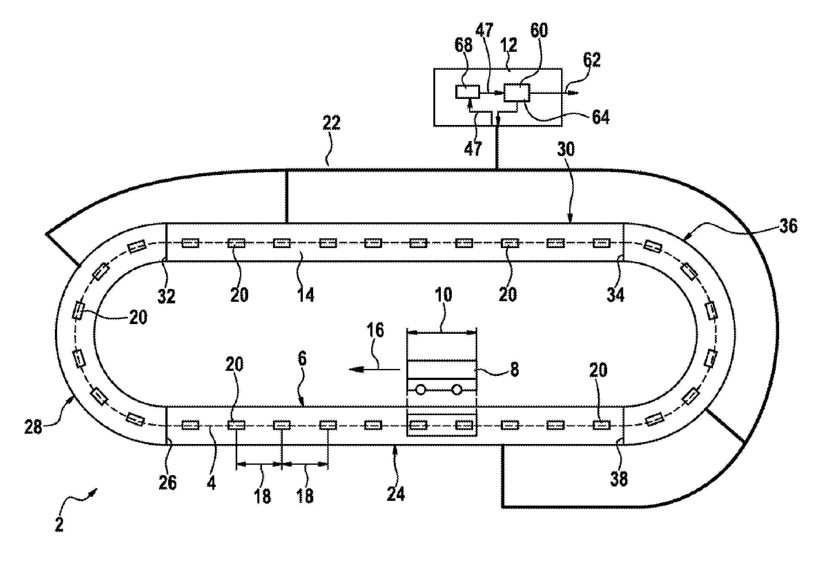
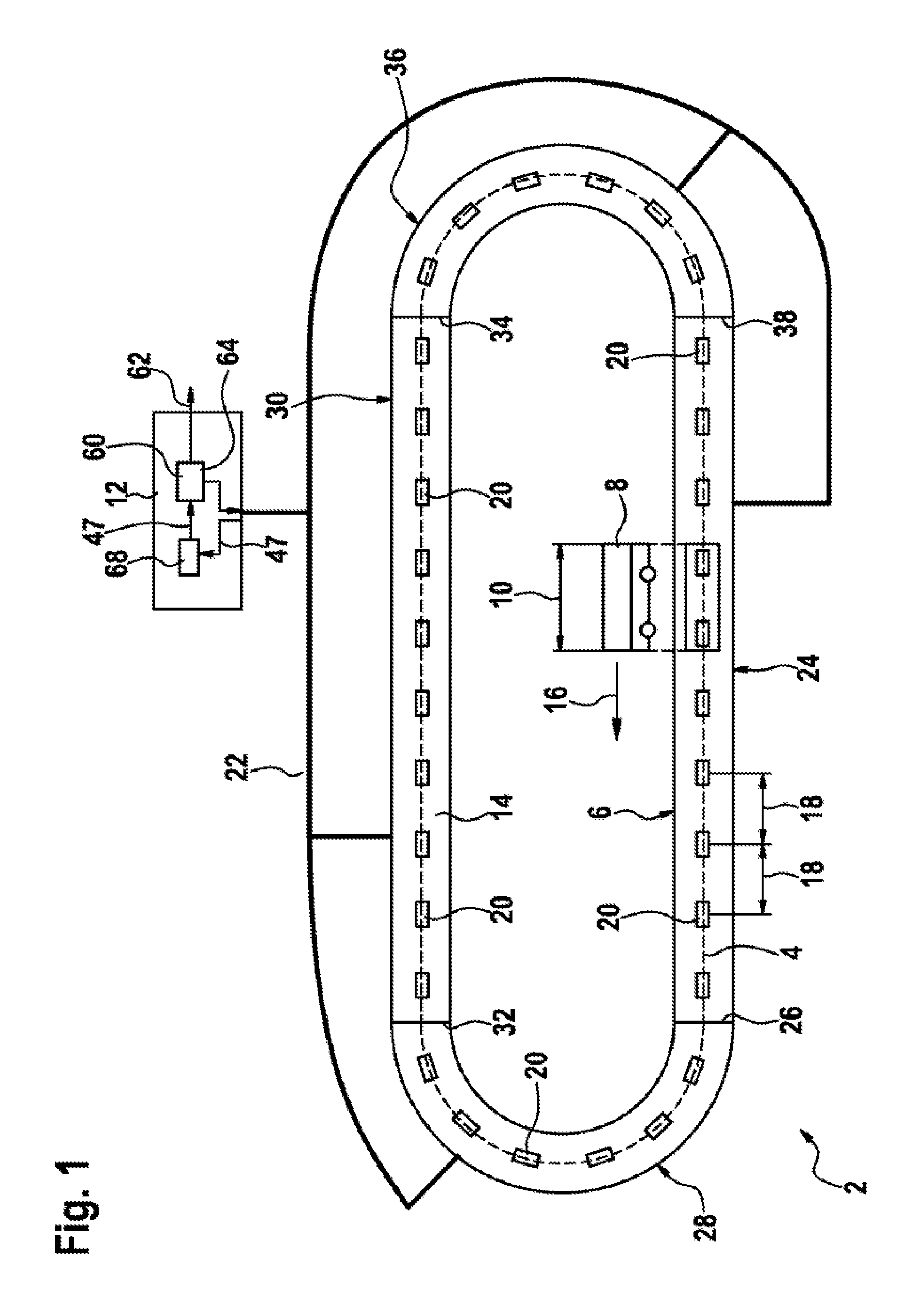
[0026]FIG. 1 schematically shows the construction of the transportation apparatus 2 with an individual sensor track 4. The transportation apparatus 2 comprises a running rail 6, a conveying element 8 with a predetermined conveying element length 10 and a measurement device 12. The transportation apparatus 2 transports products between various points on the running rail 6 using the conveying element 8.

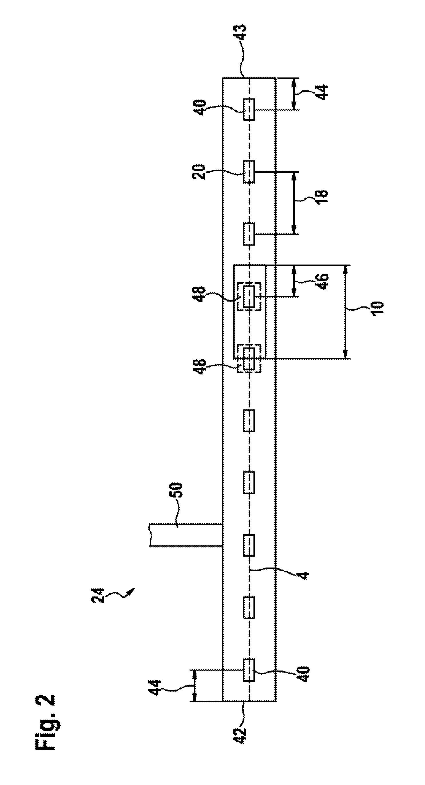
[0027]The running rail 6 is closed all the way around and has a running path 14 which defines a running distance for the conveying element 8. The sensor track 4 is embedded in the running track 14, and therefore the conveying element 8 can move back and forth in a specific running direction 16 on the running rail 6 and over the sensor track 4. By way of example, the sensor track 4 extends over the center line ...


PUM


Abstract

A transport apparatus (2) for conveying a product is disclosed. The transport apparatus (2) comprises a movable conveying element (8) which is intended to convey the product and has a pattern (52) which extends over a predetermined pattern length (66) in the direction of movement (16) of the conveying element (8) and has a multiplicity of travel increments (56, 58); a stationary, peripherally arranged running rail (6) which defines a running path (14) for the conveying element (8) and has a multiplicity of position sensors (20) on the running path (14), the distances (18) between which are shorter than the pattern length (66); and a measuring device (12) which is designed to determine an instantaneous position of the conveying element (8) on the running path (14), wherein, when the pattern enters and / or exits the measuring region (48) of a position sensor (20), the measuring device (12) determines the instantaneous position with respect to a reference position of the conveying element (8) on the running path (14), said reference position being derived from the position of the corresponding position sensor (20), monitors at least one of the position sensors (20), in the measuring region (48) of which the conveying element (8) is located, and increments or decrements the instantaneous position if a travel increment (56, 58) passes a position sensor (20) being monitored.

Description

BACKGROUND OF THE INVENTION[0001]Transportation apparatuses for conveying products for filling packaging machines, for example for chocolate bars, bags, bottles etc., generally comprise moveable conveying elements, called carriers, which are provided for conveying the product, and a stationary, revolving running rail which defines a running path for the carriers.[0002]Incremental travel measurement systems are used for the parallel, that is to say simultaneous, determination of the carrier positions of the individual carriers in transportation apparatuses of this kind. To this end, a grid, also called an incremental track, is generally provided on the side of the transportation apparatus which is fixed to the frame, and an incremental sensor is provided on the carrier, this incremental sensor allowing the passed travel increments of the grid to be counted during the run and thus allowing the position of the carrier in the transportation apparatus to be determined.[0003]The increment...

Claims


Application Information

Patent Timeline
Patent Type & Authority Applications(United States)
IPC IPC(8): B65G43/08
CPCG01D5/245
Inventor REINISCH, MARTIN
Owner ROBERT BOSCH GMBH
Why Eureka
Try Eureka