Brake-Hydraulic-Pressure Control Device

a control device and hydraulic pressure technology, applied in brake action initiation, brake components, brake systems, etc., can solve the problems of difficult control of input hydraulic pressure and complicated construction, and achieve the effect of improving the brake hydraulic pressure control devi

Inactive Publication Date: 2016-02-25
TOYOTA JIDOSHA KK
View PDF8 Cites 11 Cited by
  • Summary
  • Abstract
  • Description
  • Claims
  • Application Information

AI Technical Summary

Benefits of technology

[0008]The stiffness of the working fluid in the input chamber is large (noted that the stiffness is obtained by dividing an amount of change in hydraulic pressure by an amount of change in an amount of the working fluid). Thus, when working fluid is supplied to the input chamber at a high flow rate, satisfactory control of the input hydraulic pressure is difficult due to, e.g., rapid increase in the input hydraulic pressure. However, the stiffness of working fluid in the input chamber can be reduced by connecting at least one brake cylinder to the input chamber. This reduction of the stiffness can satisfactorily reduce rapid increase in the input hydraulic pressure, thereby improving controllability of the input hydraulic pressure. On the other hand, the regulator can be configured to have a damper chamber capable of absorbing change in the hydraulic pressure in the input chamber, but other problems are caused such as a complicated construction of the regulator. In contrast, the present brake-hydraulic-pressure control device eliminates the need for forming a damper chamber in the regulator, avoiding a complicated construction of the regulator accordingly.CLAIMABLE INVENTIONS
[0092]In the case where the hydraulic brake system is normal, a large-diameter pressurizing state is established (in which the area of the pressurizing face is substantially large). This construction can reduce the stroke of the pressurizing piston in the case of the same amount of working fluid supplied to the brake cylinder connected to the pressure chamber. Also, in the event of malfunction in the electrical system, a small-diameter pressurizing state is established (in which the area of the pressurizing face is substantially small). This construction can increase the hydraulic pressure in the pressure chamber in the case of the same forward force applied to the pressurizing piston, thereby making the hydraulic brake system more fail-safe.

Problems solved by technology

Thus, when working fluid is supplied to the input chamber at a high flow rate, satisfactory control of the input hydraulic pressure is difficult due to, e.g., rapid increase in the input hydraulic pressure.
On the other hand, the regulator can be configured to have a damper chamber capable of absorbing change in the hydraulic pressure in the input chamber, but other problems are caused such as a complicated construction of the regulator.

Method used


Image

  • Brake-Hydraulic-Pressure Control Device
  • Brake-Hydraulic-Pressure Control Device
  • Brake-Hydraulic-Pressure Control Device

Examples


first embodiment

Configuration of Hydraulic Brake System

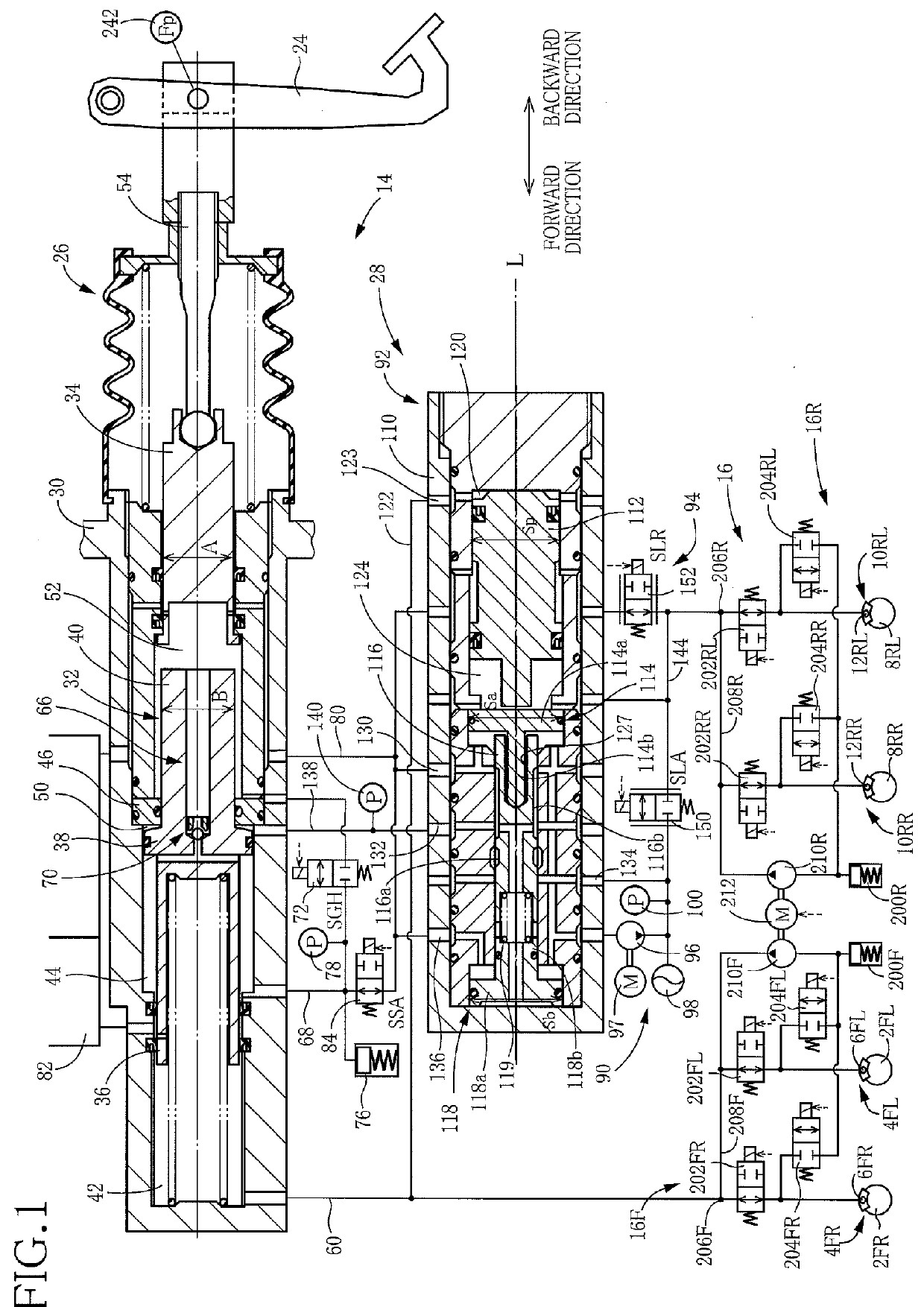
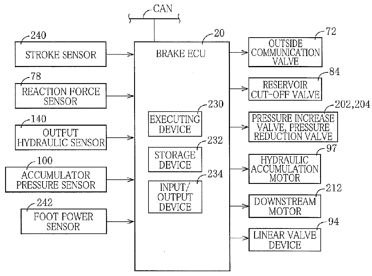
[0109]As illustrated in FIG. 1, the hydraulic brake system includes: brake cylinders 6FL, 6FR of hydraulic brakes 4FL, 4FR provided on respective front left and right wheels 2FL, 2FR; brake cylinders 12RL, 12RR of hydraulic brakes 10RL, 10RR provided on respective rear left and right wheels 8RL, 8RR; a hydraulic-pressure producing device 14 capable of supplying hydraulic pressure to these brake cylinders 6FL, 6FR, 12RL, 12RR; and a slip control device 16 provided between the hydraulic-pressure producing device 14 and the brake cylinders 6FL, 6FR, 12RL, 12RR. Devices including the hydraulic-pressure producing device 14 and the slip control device 16 are controlled by a brake ECU 20 (see FIG. 2) mainly constituted by a computer.

[0110]Hydraulic-Pressure Producing Device

[0111]The hydraulic-pressure producing device 14 includes: a brake pedal 24 as a brake operating member; a master cylinder 26; and a rear-hydraulic-pressure control device 28 config...

second embodiment

[0174]FIG. 4 illustrates a hydraulic brake system according to a second embodiment. The hydraulic brake system illustrated in FIG. 4 differs from the hydraulic brake system according to the first embodiment in, e.g., a construction of the regulator. It is noted that the same reference numerals as used in the first embodiment are used to designate the corresponding elements in FIG. 4, and an explanation and drawings of which are dispensed with.

Configuration

[0175]A regulator 300 includes a pilot piston 304, the spool driving member 114, the spool 116, and the opposed piston 118 provided in a cylinder bore formed in a housing 302. The pilot piston 304, the spool driving member 114, the spool 116, and the opposed piston 118 are arranged in the direction parallel with the axis L so as to be slidable in this direction.

[0176]The pilot piston 304 has a fitting groove 306 formed through the pilot piston 304 in its radial direction and extending in the direction of the axis L. A rod 308 fixed...

third embodiment

[0188]FIG. 5 illustrates a hydraulic brake system according to a third embodiment. The hydraulic brake system illustrated in FIG. 5 differs from the hydraulic brake systems according to the first and second embodiments mainly in the master cylinder. It is noted that the same reference numerals as used in the first embodiment are used to designate the corresponding elements in FIG. 5, and an explanation and drawings of which are dispensed with.

Configuration

[0189]The hydraulic brake system illustrated in FIG. 5 is configured such that the cross-sectional area C of a rear small-diameter portion 402 of a pressurizing piston 400 of a master cylinder 398 is smaller than the cross-sectional area D of the input piston 34. A normally open outside communication valve 406 is provided in the outside passage 68 that connects between the separated chamber 52 and the annular chamber 44. A flow limiting device 412 is provided in a reservoir passage 410 that connects between the master reservoir 82 ...


PUM


Abstract

A brake-hydraulic-pressure control device includes: a regulator including a movable member which is driven by input hydraulic pressure as hydraulic pressure in an input chamber, the regulator being capable of controlling output hydraulic pressure using movement of the movable member; and an input-hydraulic-pressure control device capable of controlling the input hydraulic pressure to control hydraulic pressure in a plurality of brake cylinders. The plurality of brake cylinders include at least one brake cylinder as a first brake cylinder connected to the input chamber.

Description

CROSS REFERENCE TO RELATED APPLICATION[0001]The present application claims priority from Japanese Patent Application No. 2014-168246, which was filed on Aug. 21, 2014, the disclosure of which is herein incorporated by reference in its entirety.BACKGROUND[0002]1. Technical Field[0003]The following disclosure relates to a brake-hydraulic-pressure control device.[0004]2. Description of the Related Art[0005]Patent Document 1 (Japanese Patent Application Publication No. 2013-227016) discloses a brake-hydraulic-pressure control device in which a plurality of brake cylinders are connected to a pressure chamber formed in front of a pressurizing piston of a master cylinder, and a regulator is connected to a rear chamber formed at a rear of the pressurizing piston. In the regulator, a spool is moved by hydraulic pressure in an input chamber, namely, input hydraulic pressure, to control output hydraulic pressure. An accumulator is connected to the input chamber via a linear valve, and the inpu...

Claims


Application Information

Patent Timeline
Patent Type & Authority Applications(United States)
IPC IPC(8): B60T13/68B60T13/14
CPCB60T13/686B60T13/148B60T13/142B60T13/68B60T7/042B60T13/146B60T13/662
Inventor ISONO, HIROSHI
Owner TOYOTA JIDOSHA KK
Why Eureka
Try Eureka