Data link control device

a control device and data link technology, applied in the direction of digital transmission, data switching network, electrical apparatus, etc., can solve the problems of low connection rate and bad communication quality of the subscriber uni

Inactive Publication Date: 2003-09-18
SYNCOMM TECH
View PDF1 Cites 19 Cited by
  • Summary
  • Abstract
  • Description
  • Claims
  • Application Information

AI Technical Summary

Problems solved by technology

For this, it often causes inappropriate link between functions of state management and data transmission, which leads to implementation problems of difficulties in debugging and designing, or even causes bad communication quality for a subscriber unit, such as low connection rate, or information interruption due to data link transfer failed.

Method used


Image

  • Data link control device
  • Data link control device
  • Data link control device

Examples


Embodiment Construction

[0019] Referring now to the drawings, in which same numerals represent same elements, a data link control device in accordance with a preferred embodiment of the invention will be described.

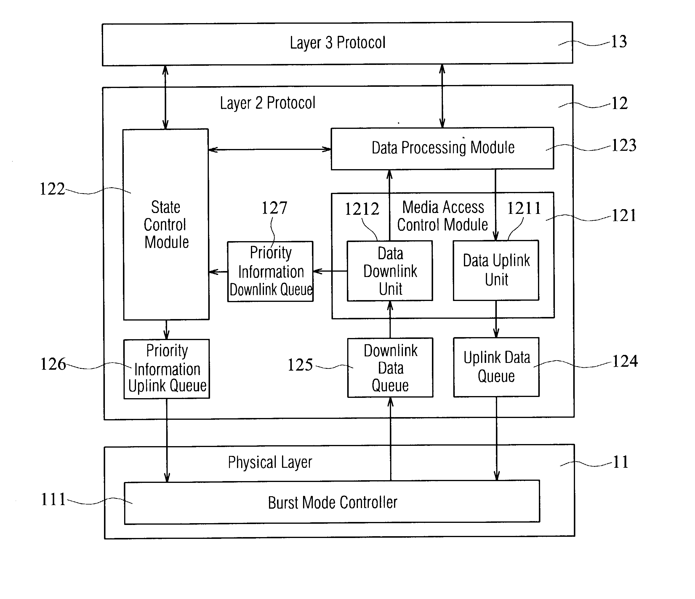
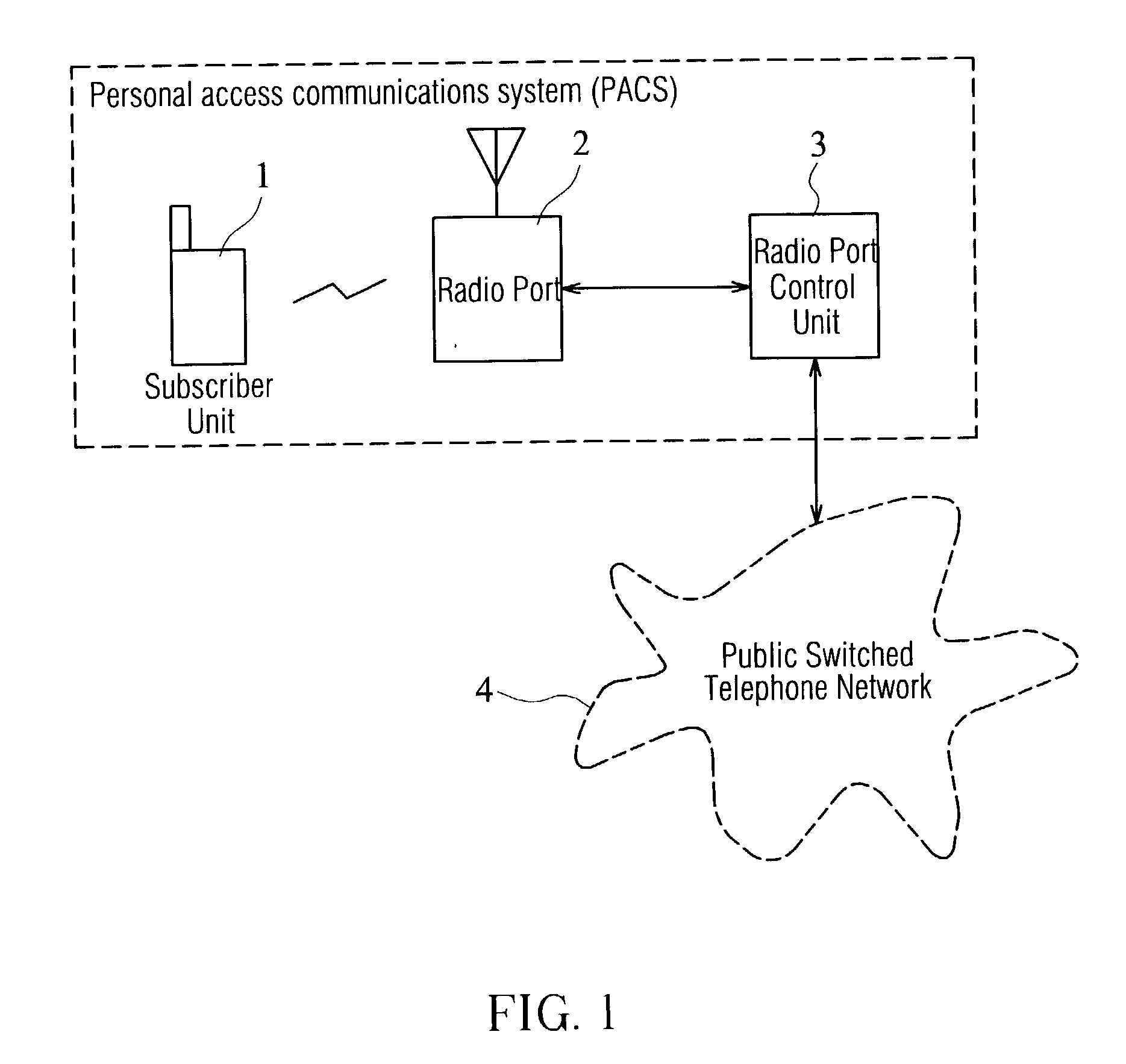
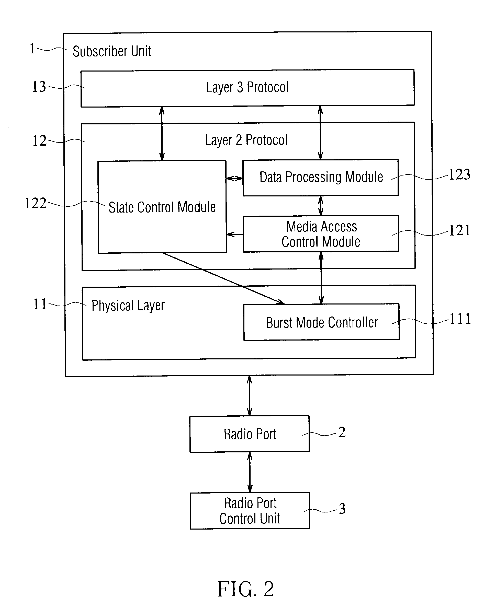
[0020] As shown in FIG. 2, the data link control device in one embodiment of the invention is implemented in a Layer 2 Protocol 12 of a subscriber unit 1 to establish and maintain data link between the subscriber unit 1 and the radio port 2. The subscriber unit 1 further includes a physical layer (that is, Layer 1 Protocol 11) and a Layer 3 Protocol 13. The physical layer 11 carries out actual data transmission tasks through a transmission media. It includes a burst mode controller (BMC) 111, which works as an interface between the physical layer 11 and the Layer 2 Protocol 12. The Layer 3 Protocol 13 executes procedures for registering, and dialing, receiving, and disconnecting calls in the subscriber unit 1.

[0021] As shown in FIG. 3, the data link control device in one embodiment of the inventi...


PUM


Abstract

A data link control device which is implemented in a Layer 2 Protocol of a subscriber unit in order to establish and maintain data link between the subscriber unit and a radio port. In which, the Layer 2 Protocol is located between a physical layer and a Layer 3 Protocol. The data link control device comprises a media access control module, a state control module and a data processing module. The media access control module transmits and receives data between the subscriber unit and the radio port. The state control module controls and manages the flow of states of the subscriber unit. States in the state control module can be classified as Off State, Acquiring State, Standby State, and Active State. According to system information channel (SIC) message and alerting channel (AC) message received, or requests from the state control module, the data processing module carries out corresponding actions to the state control module. Also, the data processing module uses acknowledged mode transfer (AMT) communication protocol and through the media access control module, uplinks and downlinks information to and from a radio port control unit, in order to transmit information of Layer 3 Protocol between the subscriber unit and the radio port control unit. In which, the AMT communication protocol instructs the information receiver to feed back the correctness of the information transmitted.

Description

[0001] 1. Field of the Invention[0002] The invention relates to a data link device and, more particularly, to a data link control device that centrally controls the states of a subscriber unit, and uses modularized concept to distinguish state control from data control.[0003] 2. Description of the Related Art[0004] Along with the progress in wireless communication technology, a subscriber unit has become one of the most popular communication tools. In a subscriber unit, the communication protocol can normally be divided into three layers. The first layer is a physical layer, which uses a transmission media to carry out actual data transmission. Layer 3 Protocol executes procedures for registering and dialing, receiving, and disconnecting calls in a wireless communication device. Layer 2 Protocol is in charge of establishing data link, maintaining and releasing the link.[0005] FIG. 1 shows the structure of a personal access communications system (PACS), which will be used as an examp...

Claims


Application Information

Patent Timeline
Patent Type & Authority Applications(United States)
IPC IPC(8): H04L12/56H04L29/08
CPCH04W28/14H04W72/12H04L69/325H04L69/323H04L69/324H04L69/32H04L69/321
Inventor HSUEH, YU-JENCHEN, HSI-KUN
Owner SYNCOMM TECH
Why Eureka
Try Eureka