Leading ground contact with the aid of a spring element

Inactive Publication Date: 2014-03-27
ROBERT BOSCH GMBH
View PDF6 Cites 7 Cited by
  • Summary
  • Abstract
  • Description
  • Claims
  • Application Information

AI Technical Summary

Benefits of technology

The purpose of this invention is to create an electrical plug connection with a leading ground contact that is durable and doesn't take up too much space in the plug direction.

Problems solved by technology

All of the above-mentioned approaches may have the disadvantage that they must be expensively retrofitted during the retrofitting of existing projects which use the plug connection.
Since the corresponding contact element differs from the other electrical contact elements, it is subjected during the plugging together to different mechanical strains than the remaining contact elements, which may result in increased susceptibility to wear of the leading ground contact.
The lengthening of the ground contact element may also have the result that an installation space enlargement results in the plug direction in the case of the plug connection or the affected plug connector.
In the case of plug connections which include a circuit board, damage to the electrical contacts, which are not designed to be leading, may additionally occur during the plugging together of the plug connection, since the front edge of the circuit board in the case of these contacts is farther away from the front edges of the lands than in the case of the leading ground lands.

Method used


Image

  • Leading ground contact with the aid of a spring element
  • Leading ground contact with the aid of a spring element
  • Leading ground contact with the aid of a spring element

Examples


Embodiment Construction

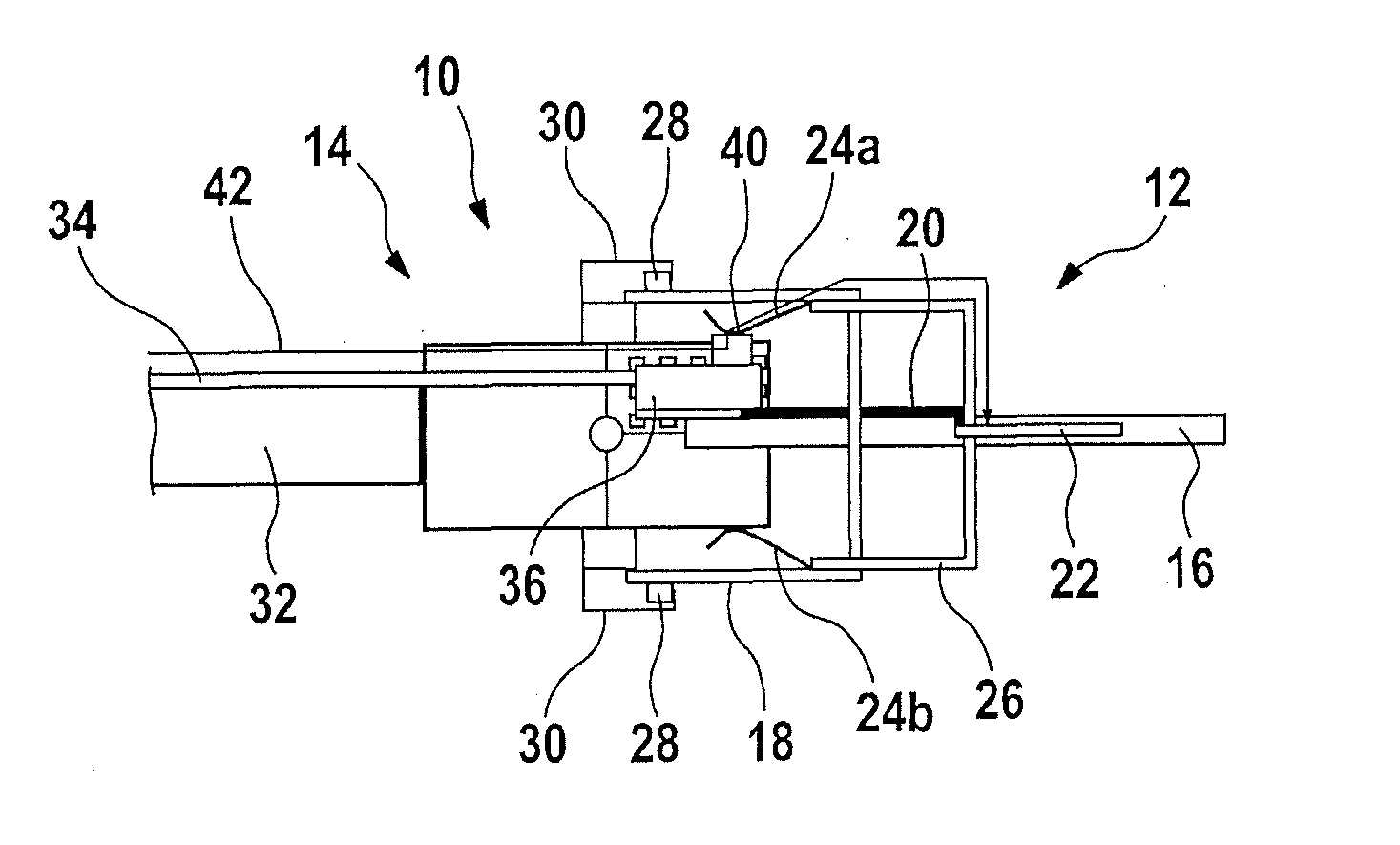
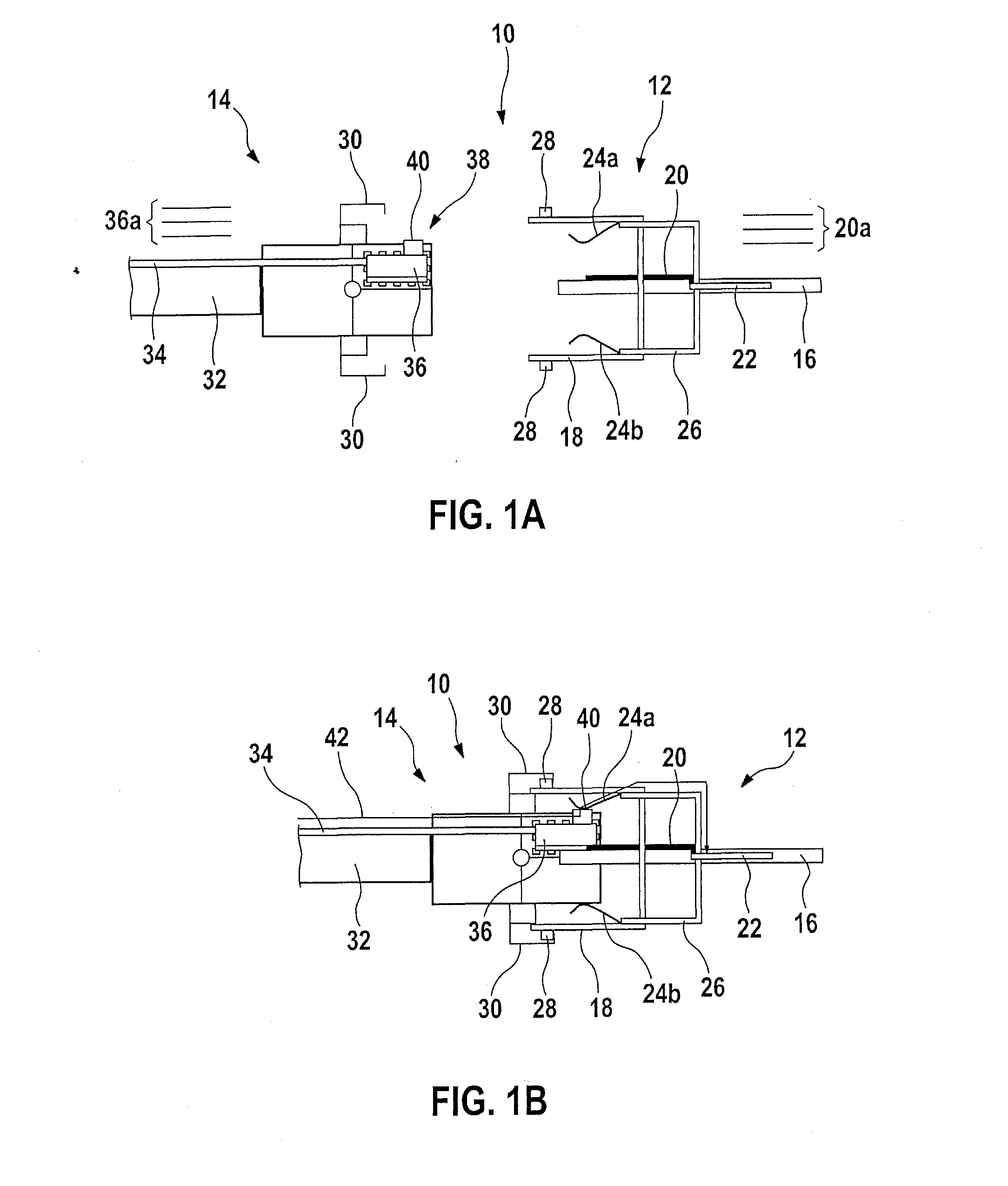
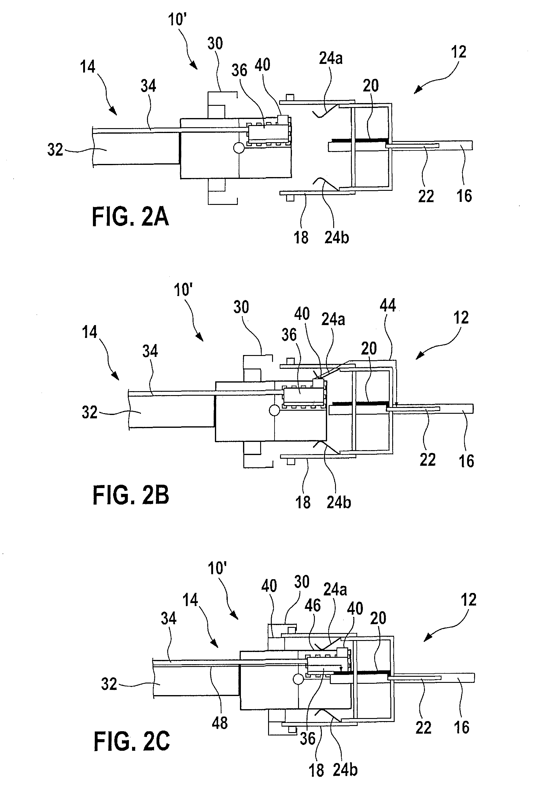
[0038]FIG. 1A shows a plug connection 10 in a longitudinal section. Plug connection 10 includes a socket 12 and a plug 14. Socket 12 is an interface for a circuit board 16, on whose edge a bush 18 is attached, which encloses the edge of circuit board 16. An electrical contact element 20 in the form of a printed conductor 20, which is connected to schematically shown ground potential 22 on the circuit board, is situated on circuit board 16. A first conductive spring element 24a and a second conductive spring element 24b are attached in each case on the inner side of bush 18 or on the interface collar wall above and below circuit board 16. Spring elements 24a, 24b may be leaf springs made of a metal strip, for example. As schematically shown in FIG. 1A, the two spring elements 24a, 24b are connected via lines 26 to ground potential 22. However, it is also possible that only lower spring element 24b or upper spring element 24a is connected to ground potential 22.

[0039]In addition, sock...


PUM


Abstract

A plug connector for connecting to a complementary plug connector includes: at least one electrical contact element for connecting to an electrical contact element of the complementary plug connector; and a spring element electrically connected to a ground line of the plug connector. The plug connector is configured in such a way that during the connection of the plug connector to the complementary plug connector, the spring element electrically contacts a ground contact element of the complementary plug connector, before the electrical contact element of the plug connector contacts the electrical contact element of the complementary plug connector.

Description

BACKGROUND OF THE INVENTION[0001]1. Field of the Invention[0002]The present invention relates to an electrical plug connector, an electrical plug connection, and a method for connecting a plug connector to a complementary plug connector.[0003]2. Description of the Related Art[0004]An electrical plug connection generally includes two electrical plug connectors, which are plugged one inside the other, to establish an electrical connection between electrical contact elements of one plug connector and the electrical contact elements of the other plug connector. Normally, one electrical plug connector is designed as a plug or as a socket and the other electrical plug connector is designed as a socket or a plug complementary thereto. A socket is to be understood as a plug connector which has an opening or a cavity, which is designed for the purpose of accommodating the plug.[0005]In the case of electrical plug connectors, which are used for the purpose of connecting electronic components ...

Claims


Application Information

Patent Timeline
IPC IPC(8): H01R13/652
CPCH01R13/652H01R13/2442H01R13/24
Inventor KROECKEL, MARKUS
Owner ROBERT BOSCH GMBH
Why Eureka
Try Eureka