Cleanroom

a technology of liquid crystal display and cleanroom, which is applied in the field of cleanroom, can solve the problems of contaminated glass substrates within the cleanroom, inability to effectively draw out, and easy disturbance of airflow coming out of the filter device arranged on the ceiling, and achieve the effect of quick drawing ou

Active Publication Date: 2014-03-27
SHENZHEN CHINA STAR OPTOELECTRONICS TECH CO LTD
View PDF10 Cites 3 Cited by
  • Summary
  • Abstract
  • Description
  • Claims
  • Application Information

AI Technical Summary

Benefits of technology

[0005]It is an object of the present invention to provide a cleanroom in whic

Problems solved by technology

However, in the actual practice, the airflow coming out of the filtering device arranged on the ceiling can be readily disturbed by the movement of a transporting apparatus, and the turbulence when the airflow hits the bottom floor

Method used


Image

  • Cleanroom
  • Cleanroom
  • Cleanroom

Examples


Embodiment Construction

[0052]In order clearly explain the technology of the embodiment illustrated in the present invention, a brief and concise description will be given along with the accompanied drawings. Apparently, the embodiments illustrated in the drawings are merely some typical embodiments and which can be readily modified by the skilled in the art without any additional laborious efforts so as to transform them into other drawings, and they should all be covered by the appended claims.

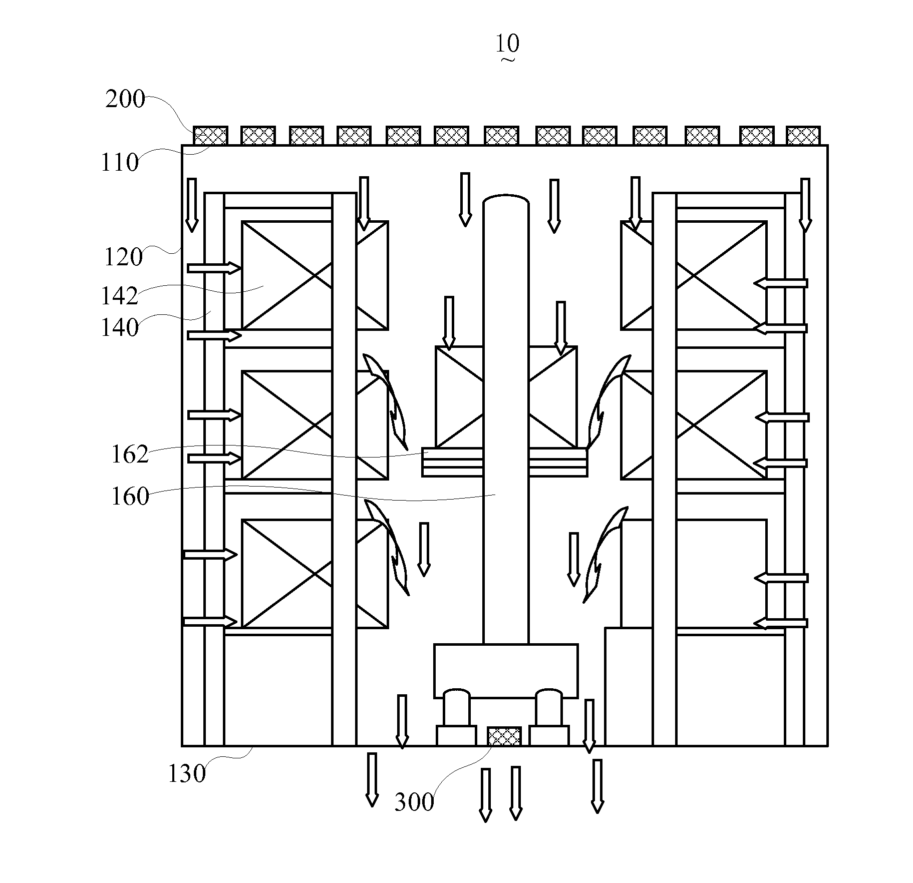
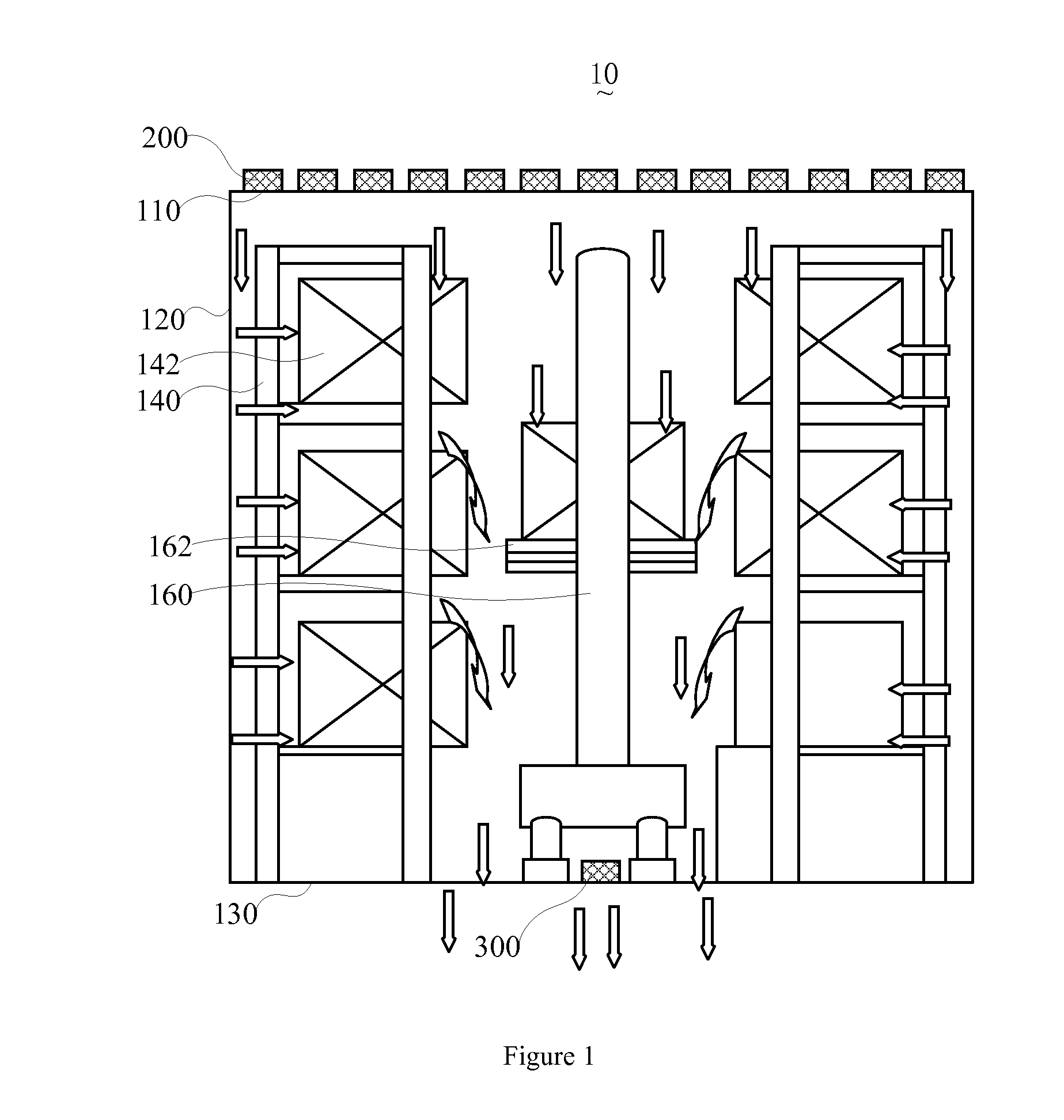
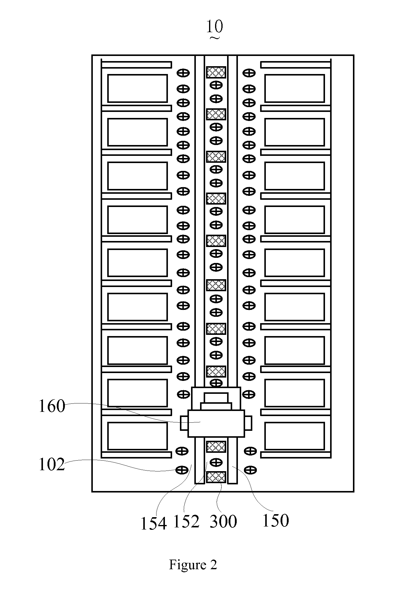
[0053]Referring to FIGS. 1 and 2, FIG. 1 is an illustrational sectional view of the cleanroom made in accordance with a preferred embodiment of the present invention, and FIG. 2 is still a cross sectional view of the cleanroom made in accordance with the present invention taken from above.

[0054]Referring to FIGS. 1 and 2, a cleanroom 10 is provided for storing glass substrates. The cleanroom 10 includes an exhaust 102, a first filtering device 200, and a second filtering device 300.

[0055]The exhaust 102 is arranged...


PUM


Abstract

The present invention provides a cleanroom for storing glass substrates, and which comprises an exhaust is disposed on a bottom floor of the cleanroom. A first filtering device is arranged on a ceiling of the cleanroom to provide purified airflow to the cleanroom. A second filtering device is arranged on the bottom floor of the cleanroom jointly to create a vertical airflow with the first filtering device so as to reduce the turbulence within the cleanroom. The present invention can readily resolve the prior art issue in which the airborne particles stirred by turbulence within the cleanroom cannot be effectively eliminated.

Description

FIELD OF THE INVENTION[0001]The present invention relates to a technical field of manufacturing of a liquid crystal display device, and more particularly to a cleanroom.DESCRIPTION OF PRIOR ART[0002]Cleanroom is also referred to as dust-free room remained with a low level of environmental pollutants, such as dust, airborne microbes, aerosol particles and chemical vapors. More accurately, a cleanroom has a controlled level of contamination that is specified by the number of particles per cubic meter at a specified particle size. In the field of manufacturing a high tech product, such as a glass substrate used to make liquid crystal display device, the cleanness, temperature and humidity of the environment have to be controlled to within a controlled range so as to ensure the glass substrate manufactured therefrom meet the preset requirements.[0003]In the existing cleanroom, an inlet with a filter is arranged on a ceiling of the cleanroom so as to provide cleaning air to the cleanroom...

Claims


Application Information

Patent Timeline
IPC IPC(8): B01L1/04
CPCF24F13/28F24F3/167
Inventor JIANG, YUNSHAOWU, CHUNHAOLIN, KUNHSIENWANG, YONGQIANGSHU, ZHIYOUGUO, ZHENHUA
Owner SHENZHEN CHINA STAR OPTOELECTRONICS TECH CO LTD
Why Eureka
Try Eureka