Tire tread for a trailer-type heavy vehicle and molding component

a technology for trailers and heavy vehicles, applied in the direction of non-skid devices, transportation and packaging, other domestic objects, etc., can solve the problems of increasing the temperature of the shoulders of tires, not preventing the appearance of certain forms of wear,

Inactive Publication Date: 2014-04-03
MICHELIN & CO CIE GEN DES ESTAB MICHELIN +1
View PDF10 Cites 22 Cited by
  • Summary
  • Abstract
  • Description
  • Claims
  • Application Information

AI Technical Summary

Benefits of technology

[0009]It is an object of the invention to propose a tread pattern that reduces the abovementioned disadvantages.
[0017]In a preferred variant, each sipe, when viewed in cross section, has a zigzag shape or a wavy shape in the thickness of the tread so as to prevent, or at least reduce as far as possible, any ingress of stones into the said sipe as far as the underlying channel.
[0024]It is preferable for each protrusion to be positioned on the bottom of the channel (which corresponds to the part delimiting the said channel that is furthest away from the tread surface in the new state) rather than on the lateral walls that delimit the said channel, so as to afford the said bottom more effective protection.
[0026]It was found during testing that this tread pattern also generated less road noise.

Problems solved by technology

One solution for increasing the amount of material in contact with a roadway for a given width of tread is to widen each rib axially as far as possible towards the outside of the tread (forming what is known as the shoulders of the tire), but it has been found that adding material to this part of the tire can lead to an increase in the temperature of the shoulders of the tire.
However, this tread pattern, although compact, does not prevent the appearance of certain forms of wear associated with what is referred to as “scrubbing”.

Method used


Image

  • Tire tread for a trailer-type heavy vehicle and molding component
  • Tire tread for a trailer-type heavy vehicle and molding component
  • Tire tread for a trailer-type heavy vehicle and molding component

Examples


Embodiment Construction

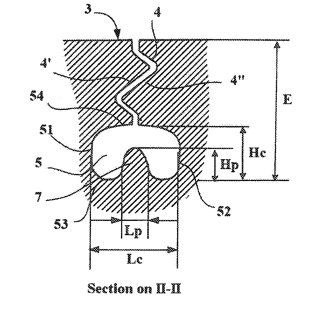
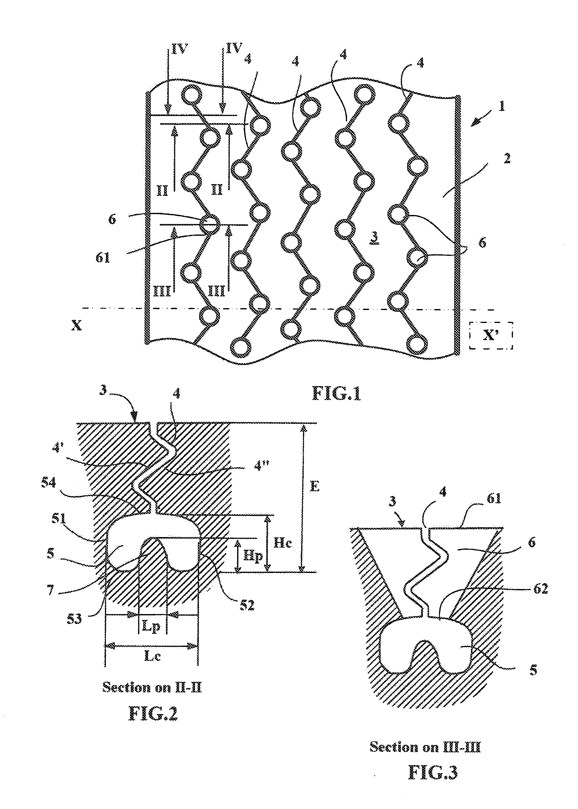
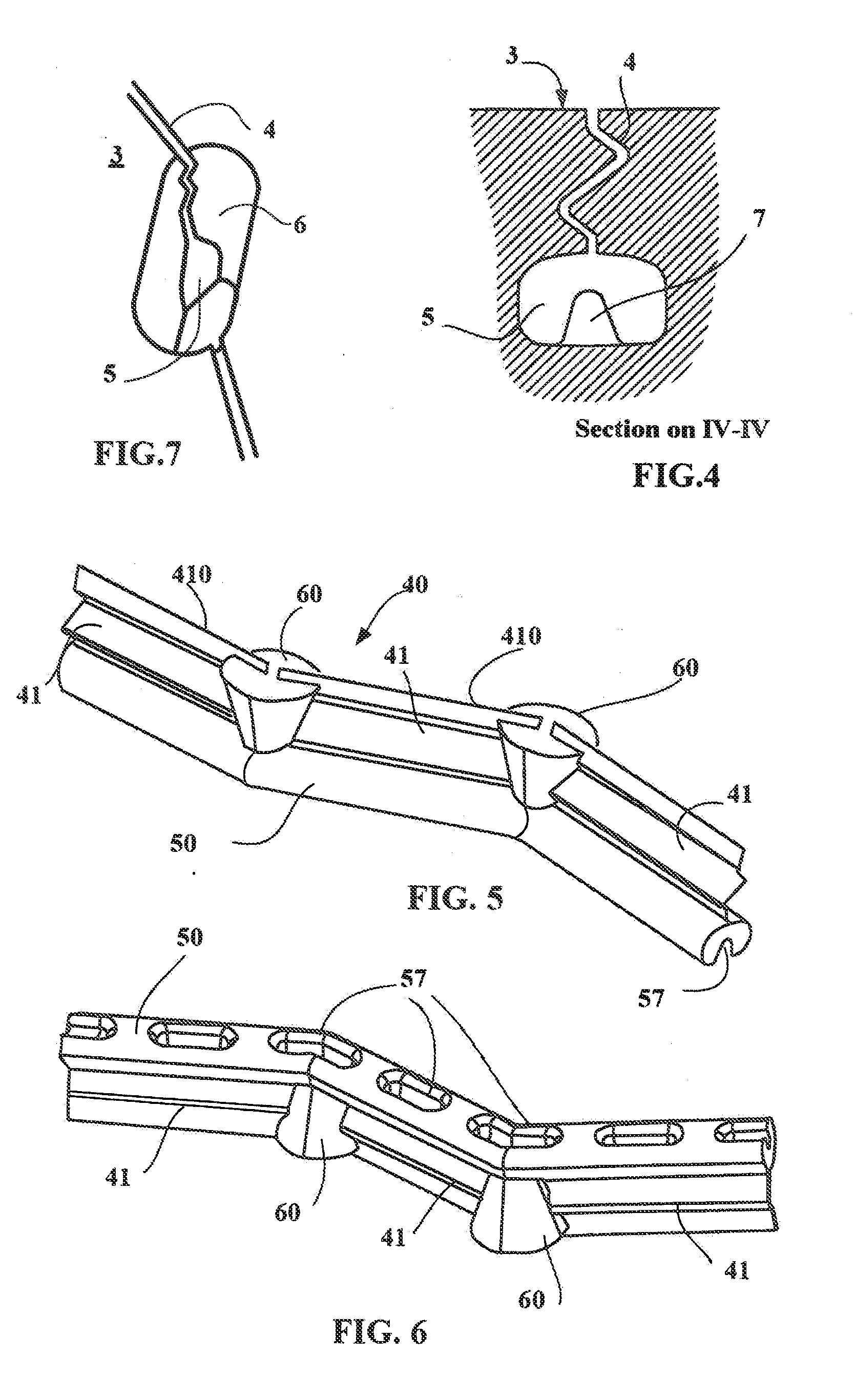
[0037]FIG. 1 shows part of the tread surface of a tread of a tire 1 of size 385 / 55 R 22.5 intended to be fitted to a heavy vehicle of the trailer type. This tire 1 comprises a tread 2 according to the invention having a thickness E of material to be worn away equal to 13.5 mm (this thickness E corresponds to a limit beyond which either the tread has to be renewed or the tire has to be changed. In this FIG. 1, it can be seen that the tread 2 has a tread surface 3 intended to come in contact with a road during running. The tread surface 3 of this tread 2 has a width TW equal to 330 mm, corresponding to the maximum contact width measured in the transverse direction (which means in a direction XX′ parallel to the axis of rotation of the tire) for conditions of use of the tire. It may be seen that this tread comprises five sipes 4 each having a zigzag line on the tread surface 3 and being oriented circumferentially overall so that each makes a complete turn around the tire in the circumf...


PUM

PropertyMeasurementUnit
thicknessaaaaaaaaaa
widthaaaaaaaaaa
widthaaaaaaaaaa

Abstract

A tread and a tire for a heavy vehicle, and a molding element therefor, this tread comprising a plurality of sipes of circumferential overall orientation and of width (Li), each of these sipes extending into the depth of the tread over a depth (P) that is less than the mean thickness (E) of the tread, each sipe being extended radially inwards by a channel having lateral walls that, when the tread has become partially worn, delimit a new groove, these lateral walls connecting to a bottom , each sipe connecting together a plurality of drainage wells, each formed in the thickness of the tread opening via a first opening onto the tread surface the maximum dimension of which is at least equal to twice the width of the sipe and via a second opening into a channel; for each sipe of circumferential overall orientation, there is at least one drainage well in the contact patch and, in the continuation of each drainage well, a protrusion on the bottom of the channel.

Description

BACKGROUND[0001]1. Field[0002]The invention relates to the treads of tires for heavy vehicles and, more particularly, heavy vehicles of the trailer type. It also relates to the tires provided with such treads.[0003]2. Description of Related Art[0004]It is known that the grip of a tire on a roadway covered with water is strongly connected with the presence of cavities which serve notably to drain away the water present between the tire and the roadway. In order to meet this performance requirement in terms of grip or road holding, it is known practice for the treads of heavy vehicles of the trailer type to have a tread pattern design made up of circumferential ribs delimiting grooves, the transverse geometry (which means the geometry viewed in the plane of section containing the axis of rotation of the tire) of the grooves being suited to avoiding the retention or jamming of stones in these grooves and thus to avoiding the bottoms of the grooves and the internal reinforcing structure...

Claims


Application Information

Patent Timeline
Patent Type & Authority Applications(United States)
IPC IPC(8): B60C11/13B29D30/06
CPCB29D30/0681B60C11/1218B60C11/042B60C11/1281B60C11/0323
Inventor FOUCHER, BENOITBECHON, HERVEMANSUY, PHILIPPE
Owner MICHELIN & CO CIE GEN DES ESTAB MICHELIN
Why Eureka
Try Eureka