
Encapsulated particles

a technology of encapsulated particles and particles, applied in the field of material systems, can solve the problems of inability to fully absorb silicon oxide, inability to absorb silicon oxide,

Active Publication Date: 2016-09-01
NANOCOMPOSIX LLC
View PDF6 Cites 44 Cited by
  • Summary
  • Abstract
  • Description
  • Claims
  • Application Information

AI Technical Summary

Benefits of technology

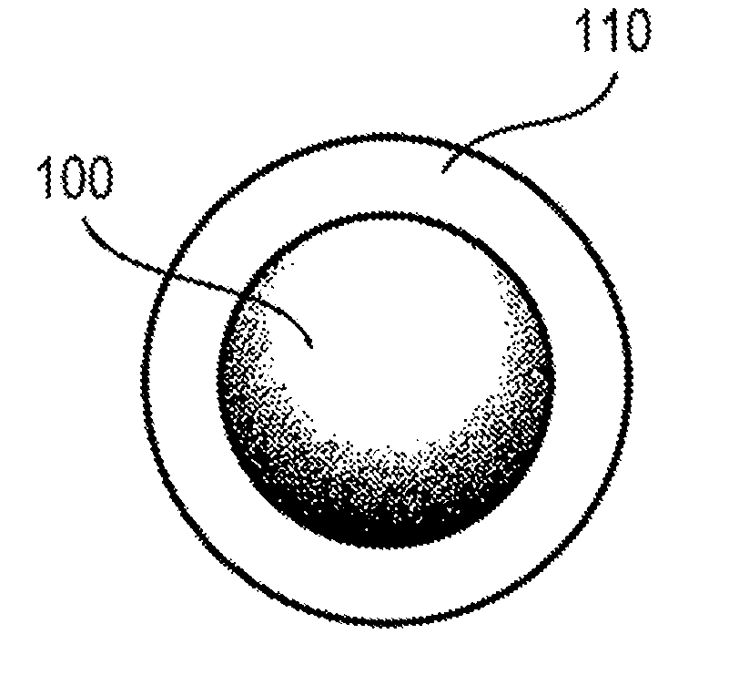
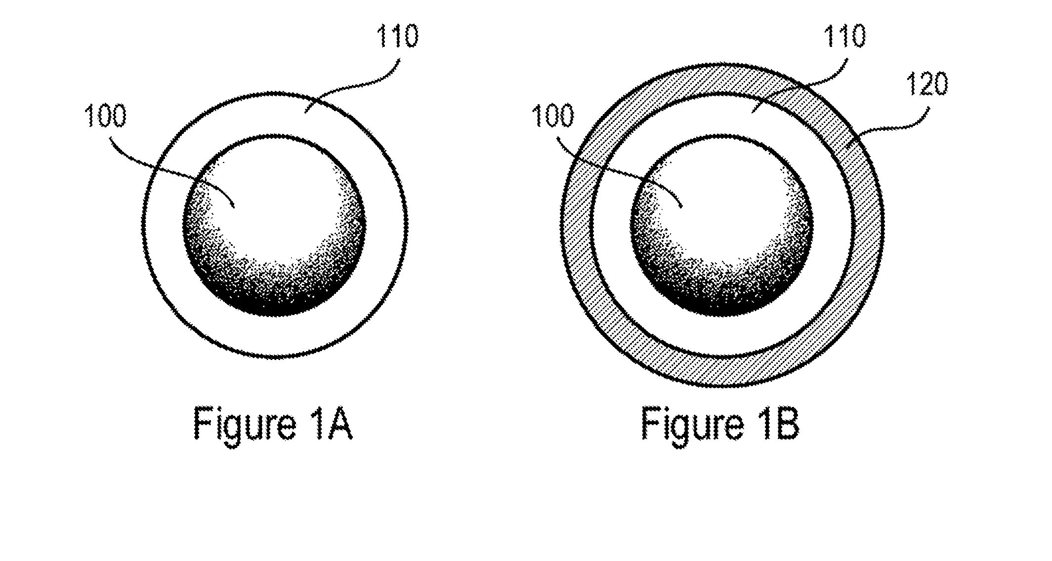
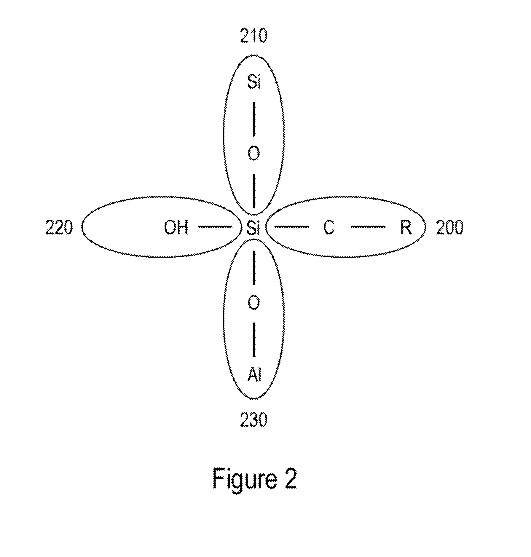
The patent describes a material composition comprising particles with a core and shell structure. The particles have a core with a maximum dimension of less than 10 microns and a shell with a thickness of less than 100 nm. The shell is made up of a network of interconnected molecular units, with each molecular unit having a chemical formula of SiOx(OH)y, where x and y are integers. The particles can be immersed in a liquid and the concentration of the particles does not change significantly after 24 hours. The material composition can also include nanoparticles that are incorporated within the particles. The nanoparticles can be quantum dots, magnetic nanoparticles, or up-converting or down-converting nanoparticles. The nanoparticles can have a core-shell structure or a different material composition than the core of the particles. The nanoparticles can have a magnetic moment or emit light. The material composition can also include a liquid in which the particles are immersed.

Problems solved by technology

However, silicon oxide, while effective against some environments, can be ineffective against some other environments.
For example, for many biological applications, particles coated with silicon oxide may be subjected to solution environments, e.g., aqueous solutions, in which silicon oxide has an unacceptable dissolution rate (e.g., nanometers within days, depending on the application).
Premature dissolution of the protective coating and the resulting exposure of the core particle surface species can be undesirable for many biological applications, since surface-bound targeting molecules can be prematurely released from the particle surface.
However, the high temperatures can increase particle agglomeration, making it difficult to redisperse the particles in uniform suspension.
While retaining the silica in an organic solvent can prevent dissolution of silicon oxide coating, such methods may not be relevant for many biological applications that require them to be maintained in an aqueous solutions.

Method used


Image

  • Encapsulated particles
  • Encapsulated particles
  • Encapsulated particles

Examples


example 1

Stability of Aluminum Silicate Shells Compared to Silicon Oxide Shells

[0151]In a 20 mL glass scintillation vial, 5 mL of 80 nm polyvinylpyrollidone (PVP) capped Biopure silver at a concentration of 1 mg / mL (nanoComposix, Inc.) was diluted with 10 mL of EtOH. The mixture was heated to 60° C. and 79 μL of 28% aqueous ammonium hydroxide solution was added followed by 18.3 μL of a 20 μL / mL solution of aminopropyltrimethoxysilane in ethanol. After fifteen minutes, 91.6 μL of a 20 μL / mL TEOS solution was added. The vial was capped and allowed to stir over night. Silicon oxide-shelled silver nanoparticles produced using this method are shown in FIG. 8.

[0152]250 μL of the silicon-oxide-shelled silver as synthesized was diluted to 1 mL in a microcentrifuge tube with either 0.1% 20000 MWT PEG solution or 5 mM AlCl3 and allowed to incubate for 10 minutes. The PEG and AlCl3 solutions were spun for 5 minutes at 10000 rpm in a microcentrifuge. The supernatant was removed and each of the solutions...

example 2

Characterization of Aluminum Silicate-Shelled Silver Nanoparticles

[0153]Aluminum silicate-shelled silver nanoparticles were analyzed to determine the core size, shell thickness and elemental composition. FIG. 8 shows the TEM image of the particles. The contrast difference in the TEM micrograph between the silver core and the silicon oxide shell can be used to determine the diameter of the core and the thickness of the shell. ImageJ software was used to analyze the images. 100 particles were counted and the core size was determined to be 83.0±6.0 nm and the shell thickness was 26.1±2.9 nm.

[0154]The elemental composition of the different components of the particle is determined by dissolution of either the core, the shell or both and subsequent measurement by ICP-MS. The aluminum silicate coated silver particle was mixed with nitric acid which diffused through the aluminum silicate shell and dissolved the silver. The silver ions were isolated from the aluminum silicate by centrifugati...

example 3

Stability of Aluminum Silicate Shells Compared to Thermally Condensed Silicon Oxide Shells

[0155]The effect of thermal treatments and aluminum treatments on silicon oxide was compared. In a 20 mL glass scintillation vial, 5 mL of 80 nm polyvinylpyrollidone (PVP) capped Biopure gold at a concentration of 1 mg / mL (nanoComposix, Inc.) was diluted with 10 mL of EtOH. The mixture was heated to 60° C. and 79 μL of 28% aqueous ammonium hydroxide solution was added followed by 18.3 μL of a 20 μL / mL solution of aminopropyltrimethoxysilane in ethanol. The solution was heated for 10 hours at 60° C. in a sealed scintillation vial. TEM analysis showed a silicon oxide shell on the gold nanoparticles after the heating step. 333 μL of the heat treated material was diluted to 1 mL with DI water, spun out at 4400 rpm in a microcentrifuge tube and resuspended in water. The supernatant was decanted, the pelleted material taken back up in 1 mL water and centrifuged again. This was then repeated a third t...


PUM

PropertyMeasurementUnit
Lengthaaaaaaaaaa
Fractionaaaaaaaaaa
Fractionaaaaaaaaaa

Abstract

The disclosed technology relates generally to material systems which include a plurality of particles and methods of making the same. The particles have a core and a shell which encapsulates the core and has at least one atomic element not included in the core. The cores of the particles have a median maximum dimension that is less than 10 microns and a median of at least one axial dimension that is between 10 nm and 500 nm. The shells of the particles have a median thickness that is less than 100 nm, a silicon concentration that is between 10% and 50% on the basis of the weight of the shells, and an aluminum concentration that is between 0.01% and 5% on the basis of the weight of the shells.

Description

BACKGROUND[0001]1. Field[0002]The disclosed technology generally relates to material systems which include a plurality of particles, and more particularly to material systems that include composite particles having a core and one or more shells that enclose the core.[0003]2. Description of the Related Art[0004]Various materials, e.g., metals and metal oxides, can be produced in the form of particles, which can have enhanced properties compared to their bulk counterparts because of, for example, their size and / or surface / volume ratio. For some applications, it may be desirable to at least temporarily prevent the particles from being exposed to external environments. One to way to limit the exposure of the particles to the external environments is to coat the particles with a protective material such as, for example, silicon oxide. Silicon oxide coatings can be formed using a variety of techniques. However, silicon oxide, while effective against some environments, can be ineffective a...

Claims


Application Information

Patent Timeline
IPC IPC(8): B01J13/20C01B33/113B22F9/16A61K9/51B22F1/02C01B33/26G01N33/543B22F1/054B22F1/102B22F1/16
CPCB01J13/20C01B33/26C01B33/113G01N33/54346B22F2302/45B22F1/02B22F9/16B22F2009/165B22F2301/255A61K9/5115C01B33/18B01J13/18C09B67/0007B22F1/0551B22F1/0553B22F1/0547B22F1/102B22F1/054B22F1/16B22F1/056C09B67/0097
Inventor OLDENBURG, STEVEN J.BALDWIN, RICHARD K.
Owner NANOCOMPOSIX LLC
Learn More